- Author Jason Gerald gerald@how-what-advice.com.
- Public 2024-01-15 08:07.
- Last modified 2025-01-23 12:04.
In mechanical engineering, gear ratio is a direct measurement of the rotational speed of two or more gears that are competitively engaged. As a general rule when dealing with two gears, if the drive gear (the gear that receives the rotary force directly from the engine, motor, etc.) is larger than the driven gear, the driven gear will rotate faster and vice versa. We can write this basic concept in a formula Gear ratio = T2/T1, T1 is the number of teeth in the first gear and T2 is the number of teeth in the second gear.
Step
Method 1 of 2: Calculating Gear Ratio in Gear Circuit
Two Gears
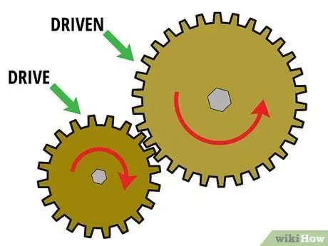
Step 1. Start with a two-gear set
In order to determine the gear ratio, you must have at least two gears interlocked. These two interlocking gears are called "gear sets". Generally, the first gear is a "drive gear" mounted on the motor shaft and the second gear is a "driven gear" mounted on the load shaft. A number of gears may also be present in between to transfer power from the drive gear to the driven gear. These gears are called "no-load gears".
Now let's look at a gear set that has only two gears in it. In order to calculate the gear ratio, these two gears must interact with each other. In other words, the teeth must mesh and one must rotate the other. For example, suppose you have a small drive gear (gear 1) that rotates a larger driven gear (gear 2)
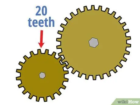
Step 2. Count the number of teeth on the drive gear
One way to calculate the gear ratio between two interlocking gears is to compare the number of teeth (small tooth-like bumps on the edge of the wheel) they have. Start by counting how many teeth are in the drive gear. You can do this by calculating manually or sometimes by looking at the information printed on the drive gear.
For example, suppose the smaller drive gear in the system has 20 teeth.
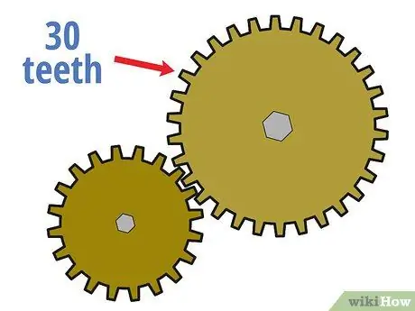
Step 3. Count the number of teeth on the driven gear
Next, count how many teeth there are in the driven gear as you did before for the drive gear.
For example, suppose the driven gear has 30 teeth.
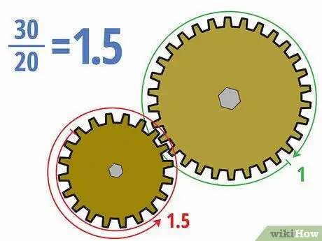
Step 4. Divide the number of teeth by one another
Now that you know how many teeth are in each gear, you can calculate gear ratios fairly easily. Divide the teeth on the driven gear by the teeth on the drive gear. You can write the answer in decimal, fractional, or ratio form (like x: y) depending on your assignment.
- In the example above, dividing 30 teeth in the driven gear by 20 teeth in the drive gear gives 30/20 = 1, 5. We can also write it in 3/2 or 1, 5: 1.
- The meaning of this gear ratio is that the smaller drive gear must rotate one and a half times for the larger driven gear to make one complete revolution. Because the driven gear is larger, the driven gear will rotate more slowly.
More Than Two Gears
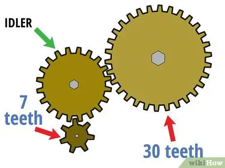
Step 1. Start with a gear set that has more than two gears
As the name implies, a "gear set" can be composed of a long series of gears, not just one drive gear and one driven gear. In this case, the first gear remains the driving gear, the last gear remains the driven gear, and the middle gear becomes the "no-load gear". These unloaded gears are often used to change the direction of rotation or to connect two gears when direct gear adjustment would make them heavy or unavailable.
For example, suppose the two-gear circuit described above is now driven by a gear that has seven tiny teeth. In this case, the gear that had 30 permanent teeth became the driven gear and the gear that had 20 teeth (which used to be the drive) is now the unloaded gear
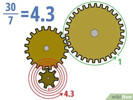
Step 2. Divide the number of teeth of the drive gear and the driven gear
The important thing to remember when dealing with gear sets that have more than two gears is that only the drive gear and the driven gear (usually the first and last gear) are important. In other words, no-load gears do not affect the gear ratios of the entire set at all. Once you have identified the drive gear and driven gear, you can calculate the gear ratios the same as before.
In the example above, we will calculate the gear ratio by dividing the thirty teeth of the driven gear by the seven teeth of the new drive gear. 30/7 = approx. 4, 3 (or 4, 3: 1). This means that the drive gear must rotate about 4.3 times for the much larger driven gear to turn once.
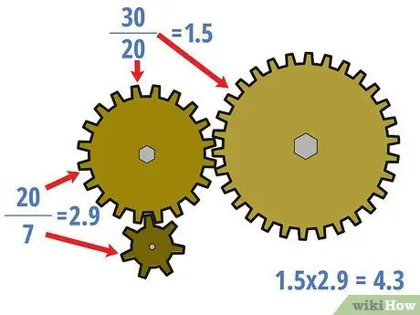
Step 3. If necessary, calculate the gear ratio for the center gear
You can calculate gear ratios that also involve unloaded gears, and you may want to do that in certain situations. In this case, start at the drive gear and work your way up to the load gear. Treat the previous gear like a drive gear all the way to the next gear. Divide the number of teeth on each "driven" gear by the number of teeth on the "drive" gear for each set of interlocking gears to calculate the center gear ratio.
- In the above example, the center gear ratio is 20/7 = 2, 9 and 30/20 = 1, 5. It should be noted that these ratios are not the same as the gear ratio for the whole set, which is 4.3.
- However, it should also be noted that (20/7) × (30/20) = 4, 3. In general, the ratios of the center gears of the gear set should be multiplied to equal the ratio of all gears.
Method 2 of 2: Making Ratio/Speed Calculations
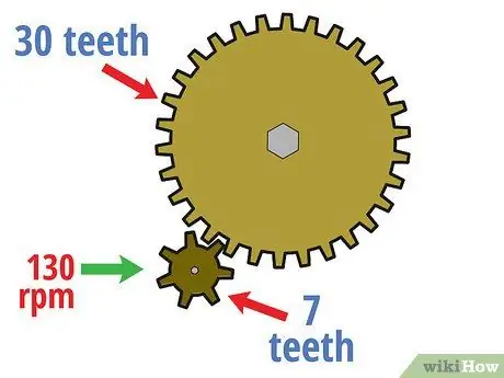
Step 1. Calculate the rotational speed of the drive gear
Using the concept of gear ratios, it is easy to determine how fast the driven gear rotates based on the "input" speed of the drive gear. For starters, calculate the rotational speed of the drive gear. In many gear calculations, this results in revolutions per minute (rpm), although other speed units can also be used.
For example, suppose in the example of the gear circuit above with a drive gear having seven teeth and a driven gear having 30 teeth, the drive gear rotates at a speed of 130 rpm. With this information, we will calculate the speed of the driven gear in the following steps
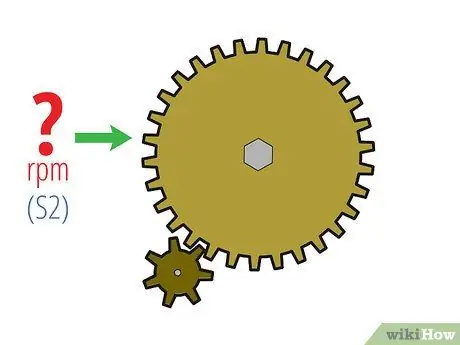
Step 2. Plug this information into the formula S1 × T1 = S2 × T2
In this formula, S1 refers to the rotational speed of the drive gear, T1 refers to the teeth of the drive gear, and S2 and T2 refers to the speed and teeth of the driven gear. Fill in these variables until you have only one variable left.
- Often in questions like this you will find the magnitude of S2, although it is possible to find other variables. In the example above, entering the information we have, we will get:
- 130 rpm × 7 = S2 × 30
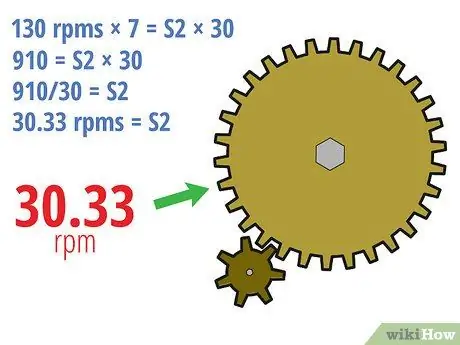
Step 3. Finish
Calculating the remaining variables is just a basic math problem. Simplify the remaining equations and isolate the variable on one side of the equation sign and you'll get the answer. Don't forget to write it in the correct units. You can lose value from homework because of this.
- In the example above, we can solve this by:
- 130 rpm × 7 = S2 × 30
- 910 = S2 × 30
- 910/30 = S2
- 30, 33 rpm = S2
- In other words, if the drive gear rotates at a speed of 130 rpm, the driven gear will rotate at a speed of 30.33 rpm. Since the driven gear is much larger, the driven gear will rotate much more slowly.
Tips
- To see how the gear ratio principle applies, try riding your bicycle. Note that the easiest way to climb is when you have a small gear in the front and a large gear in the back. It's easier to turn the smaller gear with the force of the pedals, but it takes a lot of turns for the rear wheel to turn compared to the gear setup you'd use for flat surfaces. This makes you move slower.
- A downgraded system (when the load RPM is less than the motor RPM) will require a motor that delivers optimal power at higher rotating speeds.
- The power required to drive the load is raised or lowered from the motor through the gear ratios. This motor must be resized to provide the power required by the load after the gear ratio is calculated. A raised system (when the load RPM is greater than the motor RPM) will require a motor that delivers optimal power at lower rotating speeds.


