- Author Jason Gerald [email protected].
- Public 2024-01-19 22:11.
- Last modified 2025-06-01 06:05.
Labels on multimeters can seem difficult to understand for the layman, and even people with experience in electricity may need help if they encounter an unusual multimeter with an unusual system of abbreviations. Luckily, it doesn't take long to translate the settings and understand how to read the scale, so you can get back to work.
Step
Part 1 of 3: Read Measuring Range Switch Settings
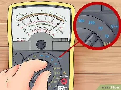
Step 1. Test the AC or DC voltage
In general, the symbol V indicates voltage, curved lines indicate alternating current (found in household electrical circuits), and straight lines indicate direct current (found in most batteries). The line can appear next to or above the letter.
- The settings for testing voltages in AC circuits are generally marked with V~, ACV, or VAC.
- To test the voltage in a DC circuit, set the multimeter to V-, V---, DCV, or VDC.
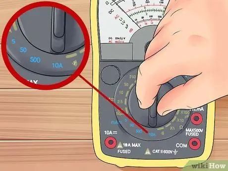
Step 2. Set the multimeter to measure the current
Since current is measured in amperes, it is abbreviated as A. Choose direct or alternating current, depending on the circuit you are testing. Analog multimeters generally do not have the ability to test alternating current.
- A~, ACA, and AAC is the symbol for alternating current.
- A-, A---, DCA, and ADC is the symbol for direct current.
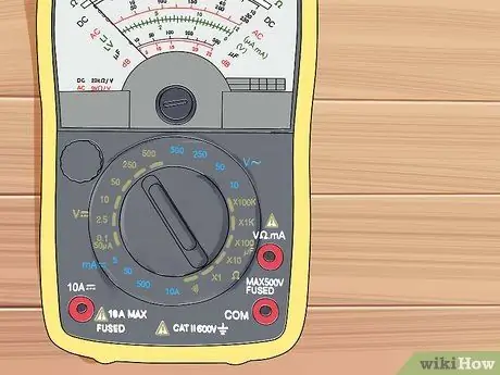
Step 3. Look for the electrical resistance setting
It is indicated by the symbol for the Greek letter omega: ️. This is the symbol used to denote the ohm, the unit used to measure electrical resistance. In older types of multimeters, this unit is sometimes denoted by the letter R for resistance.
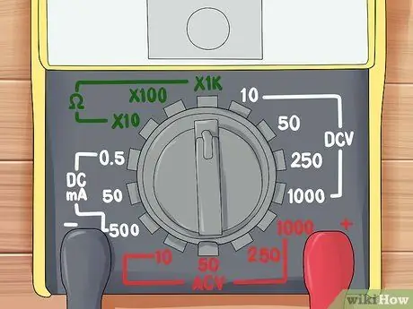
Step 4. Use DC+ and DC-
If your multimeter has this setting, use DC+ when testing direct current. If you don't get a reading and suspect that the positive and negative terminals are connected to the wrong ends, switch to DC- to correct this without having to adjust the wires.
Step 5. Understand the other symbols
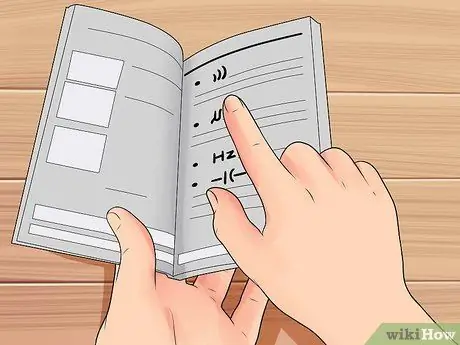
If you're not sure why there are multiple settings for voltage, current, or resistance, read the troubleshooting section for information on measuring ranges. In addition to these basic settings, most multimeters have several additional settings. If there is more than one of these signs next to the same setting, then those settings may apply to both at the same time, or you may need to refer to the multimeter user manual.
- Symbol ))) or something similar means "short circuit test". In this setting, the multimeter will sound if the two probe wires are electrically connected.
- The arrow to the right with a cross indicates "diode test", to test whether a unidirectional electrical circuit is connected.
- Hz stands for Hertz, the unit for measuring the frequency of an AC circuit.
- Symbol -|(- indicates the capacitance setting.
Step 6. Read the label on the probe cable hole
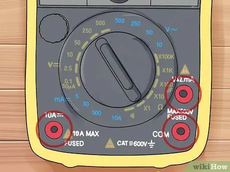
Most multimeters have three probe wire holes. Occasionally, the probe's lead holes will be labeled with symbols corresponding to the symbols described above. If the symbols are not clear, use this guide:
- The black investigator cable is always plugged into the investigator cable hole with a label COM (also known as land). The other end of the black wire is always connected to the negative terminal.
- When measuring voltage or electrical resistance, the red probe wire is plugged into the probe wire hole with the smallest current label (usually with the words mA from the abbreviation milliampere).
- When measuring current, the red probe wire is plugged into the probe wire hole with a label capable of withstanding the estimated amount of current. Usually, the probe lead for low-current circuits has a fuse 200mA, while the probe wire hole for a high-current circuit has a fuse 10A.
Part 2 of 3: Reading Analog Multimeter Results
Step 1. Find the right scale on the analog multimeter
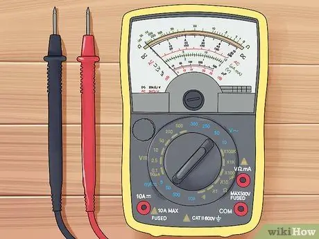
Analog multimeters have a pointer behind the glass window, which moves to indicate the result. Generally, there are three arcs printed on the back of the pointer. The bows are three different scales, each used for a different purpose:
- The scale is used to read electrical resistance. This scale is generally the largest scale, located at the top. Unlike other scales, the value of zero is on the far right rather than on the left.
- "DC" scale for measuring DC voltage.
- "AC" scale for measuring AC voltage.
- The "dB" scale is used the least. See the end of this section for a brief explanation.
Step 2. Read the voltage scale based on the measuring range
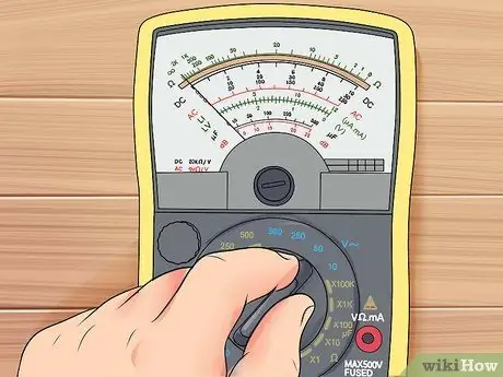
Look carefully at the voltage scale, both DC and AC. There are several rows of numbers below the scale. Check which metering range you have selected on the metering range switch (for example, 10V), and look at the appropriate label next to those lines. This is the line you should read for the measurement result.
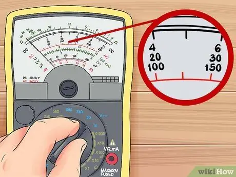
Step 3. Estimate the value between the numbers
The voltage scale on an analog multimeter is the same as on a regular ruler. But the scale for electrical resistance is logarithmic, meaning that the same distance represents a different change in value depending on where the needle is on the scale. The lines between the two numbers still represent equal divisions. For example, if there are three lines between 50 and 70, they represent 55, 60 and 65, even if the distance between them looks different.
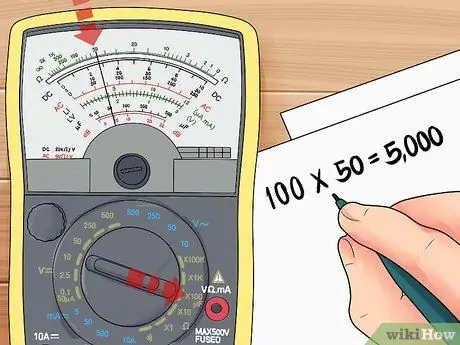
Step 4. Multiply the resistance reading on the analog multimeter
Look at the range setting indicated on the measuring range switch. This should give you a number to multiply by the reading of the measurement. For example, if the multimeter is set to R x 100 and the needle is pointing at 50 ohms, then the actual electrical resistance is 100 x 50, which is 5000.
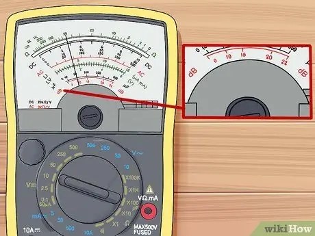
Step 5. Know more about the dB scale
The dB (decibel) scale, generally at the bottom, is the smallest in analog measurements, requiring additional training to use it. This scale is a logarithmic scale that measures the ratio of voltages (also called gain or attenuation). The American standard dBv scale defines 0 dBv as 0.775 volts measured at 600 ohms, but there are also dBu, dB, and even dBV scales (with a capital V).
Part 3 of 3: Troubleshooting
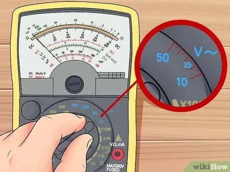
Step 1. Set the range
Unless you have a multimeter with automatic range, each of the basic modes (voltage, resistance, and current) has several settings to choose from. This is the range, which you must set before attaching the contacts to the circuit. Start with your best guess at the value which is slightly above the nearest result. For example, if you expect to measure around 12 volts, then set the measurement at 25V instead of 10V, assuming the two are the closest option.
- If you don't know the approximate current, set it to the highest range on the first try to avoid damaging the meter.
- The other way is less likely to damage the meter, but consider setting the smallest resistance and 10V as the initial measurement.
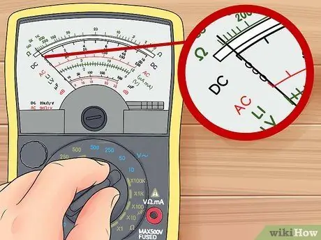
Step 2. Adjust the readings that are "off scale"
On digital meters, "OL", "OVER", or "overload" means that you should choose a higher range, while a result closer to zero means a lower range will provide better accuracy. On analog gauges, a stationary needle usually means that you should select a lower range. The pointer pointing at the maximum number means you should choose a higher range.
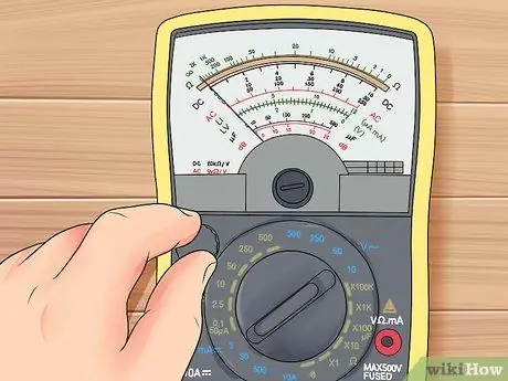
Step 3. Disconnect power before measuring electrical resistance
Turn off the power switch or remove the battery that powers the circuit for accurate measurement results. The multimeter provides a current to measure electrical resistance, and if any additional current is flowing, it will interfere with the results.
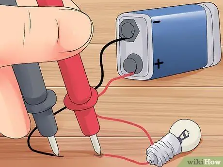
Step 4. Measure the current in the series circuit
To measure current, you must form a circuit involving a multimeter in series with the other components. For example, disconnect one lead from the battery terminals, then connect one probe to the lead and the other to the battery to close the circuit again.
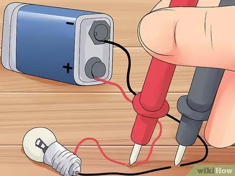
Step 5. Measure the voltage in parallel circuit
Voltage is the change in electrical energy through some part of the circuit. The circuit should be closed to the flow of current, and the measuring instrument should have two probe wires placed at different points on the circuit to connect them in parallel with the circuit.
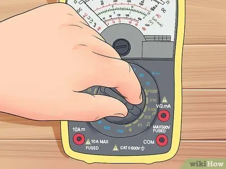
Step 6. Calibrate ohms on an analog meter
Analog meters have an additional measuring range switch, which is used to scale the electrical resistance and is usually marked with the symbol. Before taking resistance measurements, connect the two ends of the probe wire to each other. Adjust the needle position until the ohm scale reads zero to calibrate, then perform the actual test.
Tips
- If there is a mirror behind the needle of an analog multimeter, move the meter to the left or right so that the needle covers its own image for better accuracy.
- If you are having trouble reading a digital multimeter, then consult the user manual. By default, the gauge should show the reading as a number, but there can also be settings that show a bar graph or other form of information.
- If the needle of an analog multimeter shows a number below zero even at the lowest range, then your + and - connectors may be reversed. Swap connectors and read again.
- The initial measurement will fluctuate when measuring AC voltage, but it will become more stable over time to get an accurate measurement.


