- Author Jason Gerald gerald@how-what-advice.com.
- Public 2023-12-16 10:50.
- Last modified 2025-01-23 12:04.
A multimeter is a device used to check AC or DC voltage, resistance and continuity of electrical components and small amounts of current in a circuit. This tool is useful for seeing if there is a voltage in a circuit. Thus, a multimeter can help you. Start with Step 1 to familiarize yourself with the device and learn to use the different functions to measure ohms, volts, and amperes.
Step
Part 1 of 4: Familiarizing yourself with the Tools
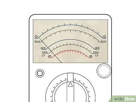
Step 1. Find your multimeter scale board
This section has a curved shaped scale that is visible through the box and a pointer that will indicate the values read from the scale.
- The curved scales on the meter box have a different color indicating each scale, so they will have different values. This determines the size of the range.
- A mirror-like reflecting surface that is curved and slightly wider may also be present. Mirrors are used to help reduce what is called "parallax error," by aligning the pointer with its image before reading the indicated value. In the image above, this surface looks like a broad gray stripe between the red and black scales.
- Many newer multimeters have a digital output rather than an analog scale. The basic function is the same, but you can read the numeric result directly.
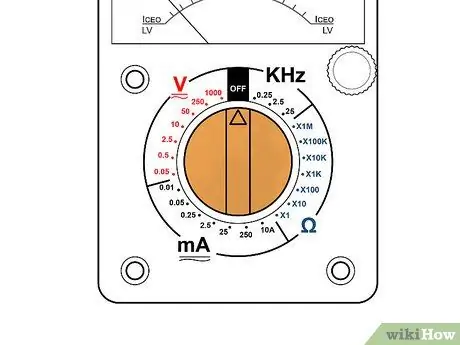
Step 2. Locate the option switch or button
This allows you to change the function between volts, ohms, and amperes and to change the scale (x1, x10, etc.) of the meter. Many multimeter functions are available in several measuring ranges. Therefore, it is important to set both of them properly. Otherwise, serious damage to the meter or a hazard to the operator will occur.
Some meters have an "Off" position on their selector switch while others have a separate switch. The multimeter should be turned off when stored and not in use
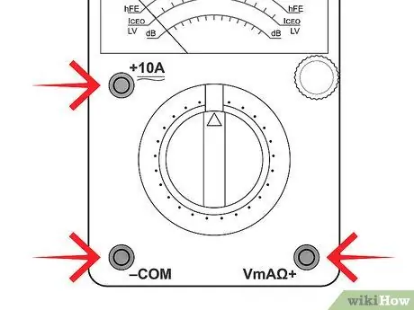
Step 3. Find the jack hole on the multimeter to insert the measuring wire
Most multimeters have multiple plugs used for this purpose.
- One is usually labeled "COM" or (-), which means common. Usually a black measuring wire is connected to this hole. This jack will be used for almost every measurement taken.
- Naturally the other available jacks will have a "V" (+) symbol and an Omega (reverse horseshoe) symbol for Volts and Ohms respectively.
- The + and - symbols represent the polarity of the measuring lead probe when making DC voltage measurements. In a standard installation, it is the red wire that will have positive polarity over the black wire. This is good to know when the circuit under test is not labeled + or -, as is usually the case.
- Many multimeters have additional jacks required for high current or voltage measurements. Connecting the wires to the correct jack holes is as important as choosing the correct measurement range and mode (between volts, amperes, ohms). All must be right. Re-read the multimeter manual if you are unsure which jack to use.
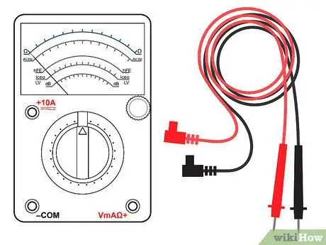
Step 4. Provide the measuring wire
There should be two cables which are generally black and red (one each). These two cables will be connected to whatever device you want to measure and test.
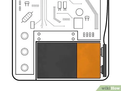
Step 5. Find the battery box and fuse
Usually this box is on the back, but some models have it on the side. This box houses a fuse (and possibly a spare) and a battery that supplies power to the multimeter to test resistance.
The multimeter may have more than one battery, which can be of different sizes. A fuse is provided to help protect the movement of the meter. Likewise, more than one fuse is often available. A good fuse is needed for the multimeter to work and a battery is needed for resistance/continuity measurement of electricity
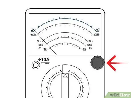
Step 6. Find the Zero Adjustment knob
This is a small knob, usually located near a button labeled "Ohms Adjust," "0 Adj," or something similar. This knob is only used for ohm or resistance measurement ranges when the probes of the measuring wires are stuck together (in contact with each other).
Turn the knob slowly to set the needle to 0 on the Ohm scale. If a new battery is installed, it should be easier - a needle that cannot point to the zero value indicates that the battery is low and should be replaced
Part 2 of 4: Measuring Resistance
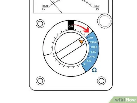
Step 1. Set the multimeter to ohms or resistance mode
Turn the multimeter to ON mode if it has a separate power switch. When a multimeter measures resistance in ohms, it cannot measure continuity because resistance and continuity are opposites. When there is little resistance, continuity will be great, and vice versa. With this, you can make assumptions about continuity based on the measured resistance values.
Look for the Ohm scale on the dial. On analog multimeters, this scale is usually at the very top and has the highest value on the left ("∞", infinity) which gradually decreases to 0 on the right. This is the opposite of the other scales, which have the lowest values on the left and the highest on the right
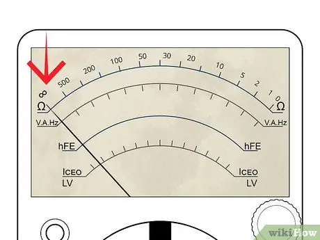
Step 2. Observe the multimeter indicator
If the measuring lead is not connected to anything, the needle or pointer of the analog multimeter will stay in the far left position, indicating an infinite resistance value or "open circuit." This is safe and means there is no continuity or current connection between the black and red wires.
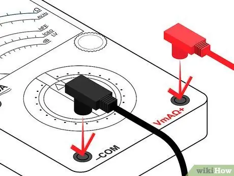
Step 3. Connect the measuring wire
Connect the black wire to the jack marked "Common" or "-". Then, connect the red wire to the jack marked with (Ohm symbol) Omega or the letter "R" next to it.
-
Set the measuring range (if available) to R x 100.
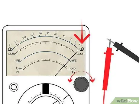
Step 4. Touch each end of the measuring wire with each other
The multimeter pointer will move to the right. Locate the zero adjustment knob marked Zero Adjust, press and rotate it so that the meter shows "0" (or as close to "0" as possible).
- Note that this position is a "short circuit" or "0 ohm" indication for this R x 1 range.
- Always remember to "zero" the meter immediately after the resistance change or you will find an error in the value.
- If you can't get to 0 ohms, this could mean the battery is low and needs to be replaced. Try doing it again with a new battery.
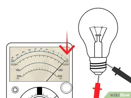
Step 5. Measure the resistance of something, for example a light bulb that is still good
Find the two points of electrical contact of the light bulb. They will be the anode and cathode.
- Invite someone who can help to hold the light bulb against the glass.
- Press the black lead on the anode and the red lead on the cathode.
- Watch the needle move, from rest on the left then fast to 0 on the right.
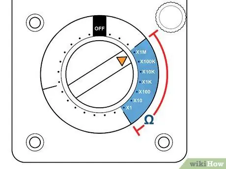
Step 6. Try different ranges
Change the measuring range to R x 1. Zero the multimeter back to this range and repeat the above steps. Observe the movement of the meter to the right which is not as fast as before. The resistance scale has been changed so that each number on the R scale can be read directly.
- In the previous step, each number represented the read value multiplied by 100. Thus, 150 = 15,000 in the previous measurement. Now, 150 is just 150. As another example, on an R x 10 scale, 150 means 1,500. The scale chosen is very important for accurate measurements.
- With this in mind, learn the R scale. This scale is not linear like other scales. Values on the left are more difficult to read than those on the right. Trying to read 5 ohms on a meter in the R x 100 range will look like 0. It's much easier to read that value on an R x 1 scale. That's why when testing resistance, we have to adjust the range first so that the reading can be taken from the center rather than the sides. left or right.
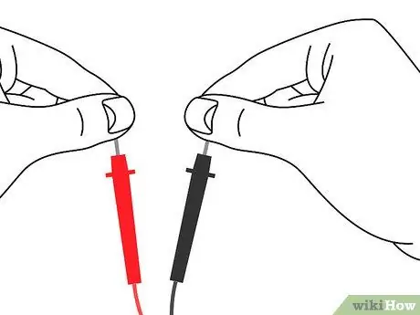
Step 7. Test resistance in hand
Use the highest possible R reading range and zero the multimeter.
- Gently attach the end of the measuring cable to each hand and read the meter. Then, try to grip the ends of the cable tightly. Watch for reduced resistance.
- Disconnect the cable and wet your hands. Hold the end of the cable again. Note that the resistance is still low.
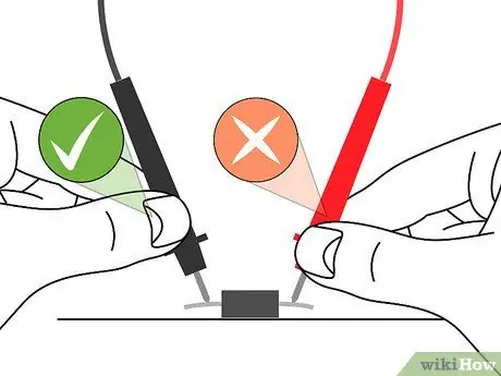
Step 8. Make sure the value reading is accurate
It is important to ensure that the end of the measuring cable does not touch anything other than the device being tested. A burnt device will not show an "open circuit" on the meter during testing if your finger provides an alternative path of current conduction, such as when touching the ends of wires.
Part 3 of 4: Measuring Voltage
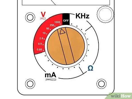
Step 1. Set the meter to use the highest range for AC voltage
In most of the cases, the voltage to be measured has an unknown value. For this reason, the highest range is chosen so that the multimeter circuit will not be damaged by a voltage that is greater than expected.
If the multimeter is set to the 50 V measurement range, plugging it into a standard 220 V power outlet can damage the multimeter and render it unusable. Start from the highest range and then lower it to the lowest range that is still able to show the voltage value
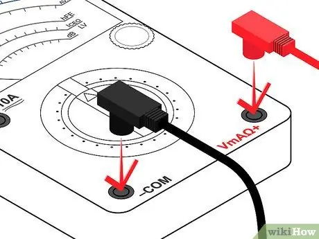
Step 2. Attach the measuring cable
Insert the black probe into the jack that says "COM" or "-". Next, insert the red probe into "V" or "+".
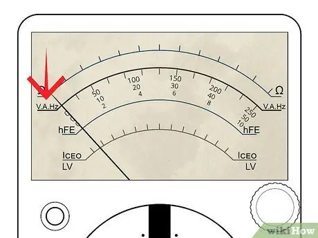
Step 3. Review the voltage scale
There may be several volt scales with different maximum values. The measurement range selected with the selector knob will determine the voltage scale that is read.
The maximum scale value must correspond to the range selected with the knob. The voltage scale, unlike the ohm scale, is linear. This scale is accurate or does not change. Of course it would be much easier to read 24 volts on a 50 volt scale than on a 250 volt scale, which would not show any significant change between 20 and 30 volts
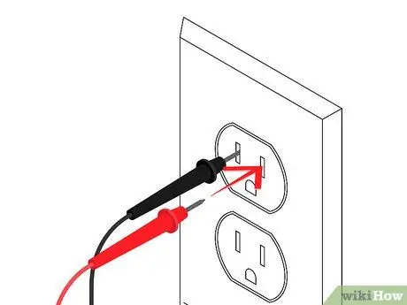
Step 4. Test the mains voltage of an outlet
In Indonesia, the value you expect is 220 volts.
- Insert the black probe into one of the socket outlet holes. After this is done it should be possible to remove the black gauge wire without swaying as the contacts on the inside will grip the probe, just like when plugging in any other electrical device.
- Insert the red probe into the other hole. The multimeter should show a voltage value of around 220 volts.
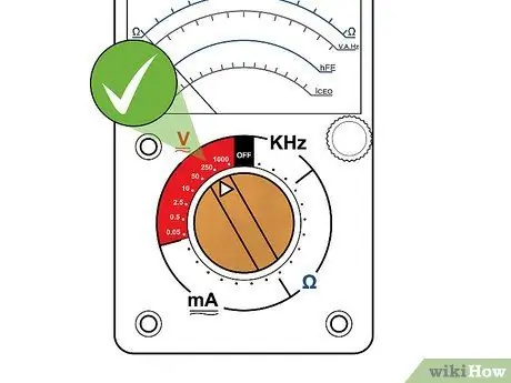
Step 5. Unplug the measuring cable
Turn the selector knob to the smallest range that can still show a readable value (220).
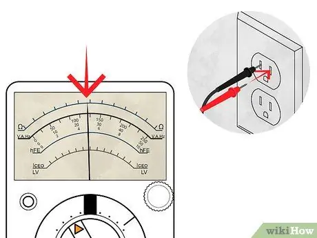
Step 6. Reconnect the cable as before
The multimeter can show a range of values between 210 and 225 volts. Range selection is important to get an accurate measurement.
- If the pointer does not move, it is possible that the selected measurement mode is DC rather than AC. AC and DC modes are not compatible. The measurement mode used must be correct. If not set correctly, users will mistakenly think there is no voltage, which can be a dangerous error.
- Be sure to try both modes if the stylus doesn't move. Set the multimeter to AC volt mode, and try again.
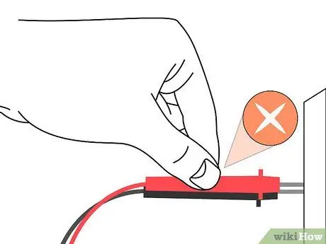
Step 7. Try not to touch both probes
Whenever possible, try to connect at least one measuring cable in such a way that you don't have to hold both of them while measuring. Some meters have accessories including alligator clips or other tweezers that will help with this. Minimizing contact with electrical circuits reduces the chances of getting burnt or injured drastically.
Part 4 of 4: Measuring Current
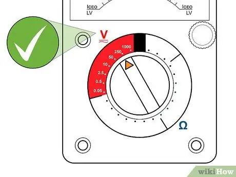
Step 1. Make sure you have measured the initial voltage
You need to determine whether the circuit is AC or DC by measuring the voltage as described in the previous steps.
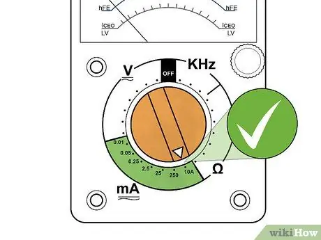
Step 2. Set the multimeter to the highest possible AC or DC amperage mode of the appliance
If the circuit to be tested is AC but the meter is only capable of measuring DC current (or vice versa), stop. The multimeter must be set to the same mode (AC or DC) as the voltage so that it does not just show a value of 0.
- Be aware that most multimeters will only measure very small currents in the A and mA range. 1 A = 0.00001 ampere and 1 mA = 0.01 ampere. This is the value of the current flowing in a typical electronic circuit, which is literally thousands (and even millions) of times less than in an automatic circuit or household electrical device.
-
Just for reference, a 100W/120V light bulb has a current of 0.833 amperes. This value may damage the meter and cannot be repaired.
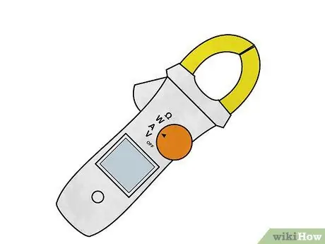
Step 3. Consider using a clamp-on ammeter
Ideal for home owners. For example, use this multimeter to measure the current through a 4700 ohm resistor at 9 volts DC.
- To do this, insert the black probe into the jack that says "COM" or "-" and insert the red pen into the jack that says "A".
- Turn off the power to the circuit.
- Open the part of the circuit to be tested (one on it or the other of the resistor). Connect the meter in series so that it closes the circuit. An ammeter is connected in series with a circuit to measure current. This cannot be done "upside down" (the multimeter can be damaged).
- Observe the polarity. Current flows from positive to negative. Set the current measurement range to the highest value.
- Turn on the multimeter and lower the current measurement range to allow for an accurate reading. Do not use too small a range to avoid damage. A reading of about 2 mA should be obtained, according to Ohm's Law, I = V / R = (9 volts) / (4700) = 0.00191 A = 1.91 mA.
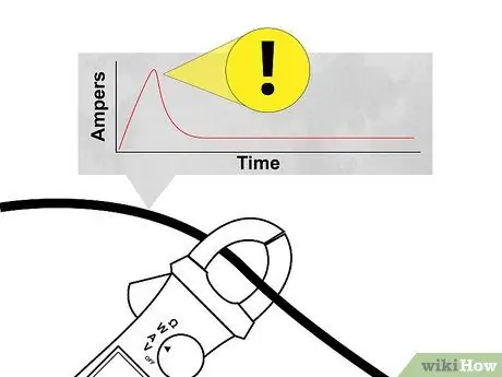
Step 4. Watch out for filter capacitors or other components that require a surge when activated
Even if the current required for operation is low and is within the fuse range of the multimeter, the surge can be many times higher, because the initial state of the filter capacitor is empty, almost like a short circuit. The fuse will almost certainly be damaged if the instrument being measured experiences a surge many times higher than the fuse rating limit. In each case, use a measuring range protected by a high value fuse and be careful.
Tips
- If the multimeter stops working, check the fuse. You can replace a damaged fuse with one purchased from an electronics store.
- When you check each section for continuity of electricity, turn off the power. Ohmmeters supply their own electricity from the internal battery. Turning on when testing resistance will damage the meter.
Warning
- Value electricity. If you don't know anything, ask and ask someone more experienced for help.
- Always check the multimeter using a good voltage source to verify its suitability before using it. A faulty voltmeter will always show 0 volts regardless of the available voltage value.
- never ever connect a multimeter to a battery or voltage source if it is set to measure current (amperes). This is one of the common causes of exploding multimeters.


