- Author Jason Gerald [email protected].
- Public 2023-12-16 10:50.
- Last modified 2025-06-01 06:05.
The first requirement in a building project is the ability to understand architectural drawings, which are also called blueprints, or floor plans. If you want to know how to read these images and understand exactly what they mean, follow these steps.
Step
Part 1 of 4: Reading the Basics

Step 1. Read the cover sheet
It contains the project name, architect's name, address and contact person, project location, and date. This page looks a lot like the cover of a book. Many cover plans also include pictures of the final product, showing what the building will look like once it's been built and landscaped.
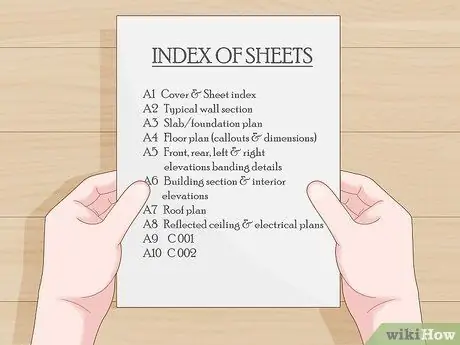
Step 2. Read the floor plan index
This page contains several index sheets of floor plans, and sometimes their contents. This sheet also contains a key to the abbreviations used, a scale bar with an indicated plan scale, and sometimes design notes are included.

Step 3. Read the location plan
It contains a map of the area, with an enlarged image of the site map, usually providing enough information to locate the project site from the nearest city or highway. This sheet is not commonly found in many plans.
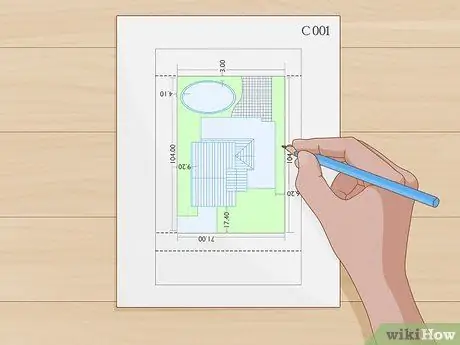
Step 4. Read the site plan
These pages are usually numbered, starting with “C”, for example Sheet “C 001”, “C 002”, and so on. The site plan contains several sheets of paper with the following information:
- Topographical information. This will inform developers and builders about the topography, slope or grade of the site area.
- Destruction plan. This sheet (can be more than one sheet) shows the structure or feature that will be destroyed at the site, such as trees, and goes to the main record.
- Site utility plan. This sheet indicates the location of “existing” underground utilities, to be protected during excavation and construction.
Part 2 of 4: Reading Architectural Sheets
Step 1. Never scale architectural drawings yourself
If you can't find any scale in the architectural drawings, get the exact scale from the architect directly.
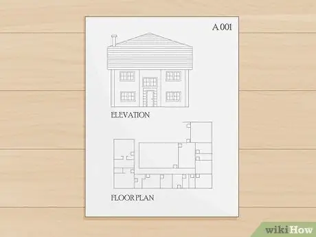
Step 2. Understand the architecture sheet
These sheets are usually marked with the letter “A”, for example “A 001”, or “A1-X”, “A2-X”, “A3-X”, and so on. This sheet illustrates and gives floor plans measurements, elevations, building sections, wall sections and other oriented views of the building design. This sheet is usually broken down into many sections and is the main construction document that you should understand. The parts that must be known are described in the following steps.
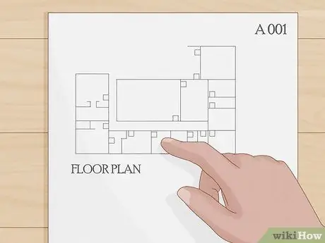
Step 3. Read the floor plan
This sheet shows the location of the walls of the building, identifying components such as doors, windows, bathrooms, and other components. There are dimensions that are recorded as the distance between, or from the center to the center of the wall, the width of the window and door openings, as well as the change in floor height if more than one story.
- Floor plans contain various levels of detail, depending on the stage of the project. In stage D (planning) the architect's drawings will probably only show the main features.
- At the tender stage, the architectural drawings will be more detailed, illustrating all existing features on a larger scale so that the contractor can price the work.
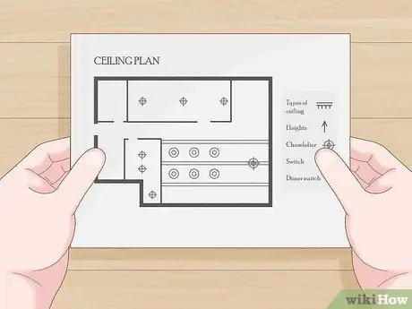
Step 4. Read the floor plan or ceiling
Here, the architect shows the type, height, and other features of the ceiling at various locations within the building. Ceiling plans may or may not exist for residential projects.
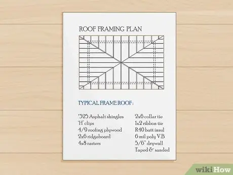
Step 5. Read the roof installation plan
This page indicates the mapping for joists, rafters, truss, joist bars, or other roof truss parts, including deck and roof mounting details.
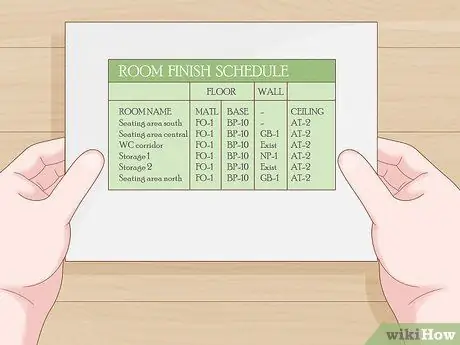
Step 6. Read the building completion schedule
It usually contains a table that describes the different finishes for each room. This list also tells the paint color for each wall, floor type and color, ceiling, height, type, and color, wall foundation, as well as notes and other details for building finishes in the listed area.
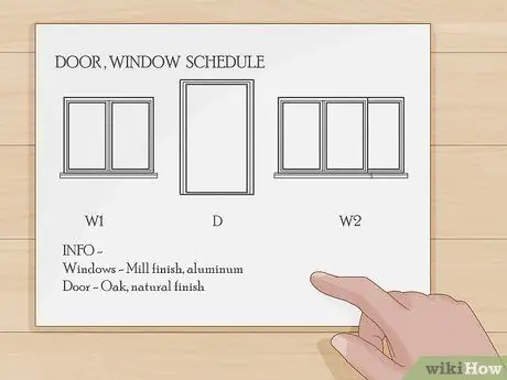
Step 7. Read the door/window installation schedule
This table lists doors, describing openings, door "handles", window information (often not included in the floor plan, eg "A", "B" type windows or doors, etc.). It may also include installation details (snippets) for flashing, installation methods, and hardware specifications. There is also a separate schedule for finishing the installation of windows and doors (though not all projects are like this). One example for windows is "Mill finish, aluminum", one of the doors is marked "Oak, natural finish".
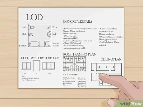
Step 8. Read the remaining details
Includes mapping of bathroom furniture, casework (cabinet), toilet accessories, and other elements not specifically noted on another sheet. For example, and not limited to: concrete cast details, doors and windows, roof installation & flashing details, wall details, door details, deck details to walls, and so on. Each project is different and includes or does not include what is included in other projects. The Detail Level (DL) or Detail Level is determined by the respective architect. A growing trend is that architects have more details, not the other way around, because then the Contractor doesn't have to guess at work and can more easily understand what to include and what to charge. Some developers may or may not have comments on TD's, but this has nothing to do with what it feels like to be properly explained in the project design by the officially licensed architect who created it.
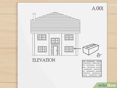
Step 9. Read the elevation or elevation
This is the exterior appearance, indicating the material used for the exterior walls, (brick, stucco, vinyl, etc.), the location of windows and doors from the side, roof slopes, and other elements visible from the outside.
Part 3 of 4: Reading the Remaining Floor Plans
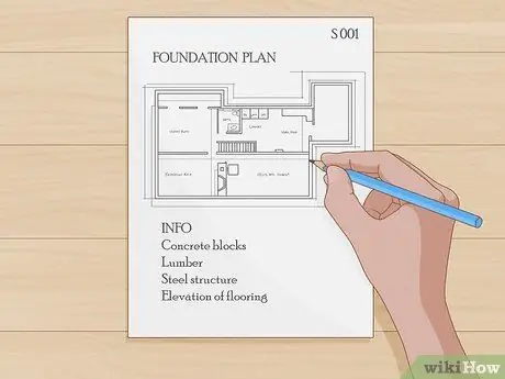
Step 1. Read the structural plan
Structural plans are usually marked starting with “S”, for example “S 001”. This plan includes reinforcement, foundation, thickness of cast concrete, and frame materials (wood, concrete pillars, structural steel, concrete blocks, etc.). The following are various aspects of structural plans that you should read:
-
Foundation plan. This sheet shows the size, thickness, and elevation of the foot or footers (footers), complete with notes on the placement of the reinforcing bars (rebar). There are also location notes for anchor bolts or solder slabs inserted for structural steel, and other elements.
The footing schedule is often shown on the start sheet of the structural record, as well as notes on what is required for reinforcement, concrete crack strength requirements, and other written statements regarding structural strength, and test requirements
- Floor plan of the frame. This sheet indicates the materials used to make the frame of the building. Usually includes metal or wood studs, concrete masonry units, or structural steel.
- Plan for the establishment of a medium structural frame. It is used for buildings with more than one story, and each level requires girders, girders, ceiling beams, deck supports, and other elements.

Step 2. Read the pipeline system plan
Plumbing pages are numbered and prefixed with a “P”. This sheet shows the location and type of plumbing system included in the building. Note: often, house design documents do not include plumbing or plumbing plans. Here are parts of the plumbing plan that you should read:
- Rough pitch. This sheet indicates the location of the plumbing system to be “stubbed-up” or “buried” to connect the plumbing system to the plumbing, sewer, and ventilation systems. This system is rarely incorporated into residential blueprints, especially single-family homes.
- Plumbing floor plan. This sheet shows the location and type of plumbing system, as well as the route the pipes will follow (over or through walls) for piped water and exhaust, as well as ventilation. This plan is commonly included, although most architects (for single-family homes) have indicated the location of the plumbing system in their floor plans.
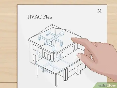
Step 3. Read the mechanical drawings
The mechanical sheet is marked with the letter “M”. This sheet shows the location of HVAC equipment (Heater = heating, Vent = ventilation, and Air Conditioner = air conditioning), culvert systems, and cooling pipes, also acts as a control wiring system. These sheets are rarely made for single-family homes.

Step 4. Read the electrical plan
Electrical plans are marked with the letter "E". This sheet shows the location of electrical circuits, panel boxes, and electrical furnishings throughout the building, including switches, sub-panels, and transformers, if they are included in the building.
- Some specialized pages in the electrical plan may contain "more elevated" details, showing power supply wiring configuration, electrical panel schedule, identification of amperage and circuit breaker ratings, as well as notes on types, sizes of electrical wires and lines.
- Some of this information may not be included in single-family house plans.

Step 5. Read the environmental plan
This is also known as a BMP (Best Management Practice) image. This sheet indicates the existing protected areas on the site, the corrosion control plan and methods of preventing environmental damage during construction. There may be some detail in the BMP drawings showing tree protection techniques, sediment fence installation requirements, and temporary rainwater drainage techniques.
Requirements for a BMP plan are obtained from the environmental protection department of your local government in your area. This may not be necessary, depending on the Territory Authority's decision for single-family housing

Step 6. Know that all plumbing, electrical, and mechanical plans are actually diagrams
Dimensions are rarely notified and it is the developer's responsibility to coordinate the placement of utilities to match building requirements and architectural drawings. Make sure that the location of the bolts matches the requirements of the device. Likewise for the electrical wiring system of fuses and switches and lights.
Part 4 of 4: Understanding Architectural Drawings Deeper
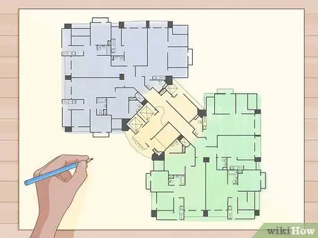
Step 1. Learn how to lay out a building trail based on an architectural plan
For this you have to find the construction elements under review, in order to be able to implement your part of the work. If you are mapping a building location, first look at the site plan to confirm the location of an existing building, structure, or property boundary, so that you have a reference point from which to start measuring the building footprint. Some plans simply give the position of the grid coordinates using the north and east angles. You need the "total station" of the surveyor's transit mode to confirm the coordinates. The following are the things you need to map the building footprint, based on the floor plan:
- Map the building on the site site based on the above-mentioned plan or measurements given on the site plan. Measure directly to the location, especially the corners, on the sides of the building, and check any "boundary points" to ensure the accuracy of your mapping. If you can't really pinpoint the exact outline of the building, you should assume that the location is correct and go further. This is generally accepted if the site is very large, so tolerable, but for crowded locations, the mapping of the location must be very precise.
- Confirm the elevation that will be where you will be working. This can be an elevation relative to the nearest highway, or based on sea level. Your site plan or architectural floor plan should have a “benchmark” height (a yardstick or benchmark refers to a number of objects, such as a manhole cover or survey path of known height) or “height above existing level” as a starting point.
-
Use your floor plan to measure the location of each corner of the building, including the offset. Remember exactly what construction elements you used for the mapping. You may mark “outer wall lines”, “foundation lines”, or “pillar lines”, depending on the type of construction and the elements most practical for making those measurements.
-
For example, if you build a steel structure with columns or pillars ' I-beam which requires setting "anchor bolts" as fasteners and securing the position, you can start mapping the building from the centerline of the pillars, while if you are building a wooden framed house with a monolithic style flat floor, then the edge of the floor can be an option. best initial mapping.
-

Step 2. List the descriptions of the various floor plans to find the construction elements to be used in the construction work
Plumbers usually use an architect's floor plan to determine the position of the wall so that the pipes to be installed are closed behind the wall when the building is made, followed by using a plumbing floor plan to determine the type and size of pipe needed for certain furniture.
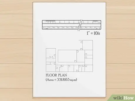
Step 3. Use a dimension scale if there is no sizing guide
Usually, architectural plans are drawn to scale. For example, 1 inch (2.5 cm) equals 10 feet (1"=10'), meaning that in the measurement between two walls on an inch-based floor plan, the actual distance is 10 feet or 3 meters. The scale rule will make this easier, but be careful to match the rule scale to the plan scale. Architects often use a fractional scale, such as the 1/32 scale, while technicians usually use the centimeters per meter scale. There are some plans or details that are out of scale, and should be marked as "(NTS)".
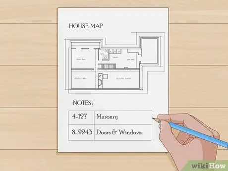
Step 4. Read all the notes on each page
Often there are certain elements that require special consideration and are easier to explain verbally than to draw. Notes on the edge of the plan is the medium used by the architect to describe. There may also be a table of notes at the margins of the plan, with numbers identifying the notes by location on the picture (numbers in circles, rectangles, or triangles) and a specific numbered statement associated, containing an explanation of the situation on the side of the plan.
- Sometimes there is a single sheet or several sheets of Numbered Drawing Notes that consolidate all or most of the floor plans for the entire set of architectural drawings. Many architects package these numbered notes into the CSI (Construction Specifications Institute) method, using 1-16 or even more Divisions which categorize drawing notes into many sub-sections.
- For example: a note reads, "4-127" might refer to a type of brick, because Division 4 represents carpentry with bricks. The note reading “8-2243” may refer to a window or door component, due to Division 8 for Doors & Windows.
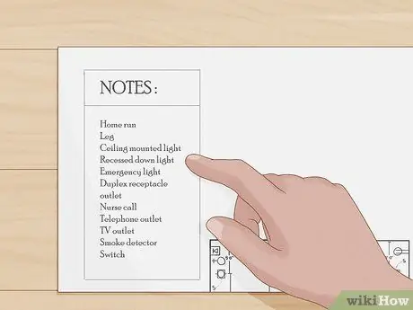
Step 5. Learn to recognize the various line drawings used by architects and engineers
You should have a table of specific keynotes for each section of the plan, and this will also provide information about the specific abbreviations, symbols, and rows used in each section of the plan.
- One example is an electrical schematic, on a circuit which may have a "home run" code "foot" (the wires from the first light junction box in a circuit to the electrical panel box) are underlined or written in darker ink than other circuits., along with other open conduit which may be indicated by a bold line, as well as closed conduit which is indicated by dots or dashed lines.
- Since there are many uses of lines to mark different types of walls, plumbing, wiring, and other features, you should refer to “key notes” on separate floor plans to understand them.
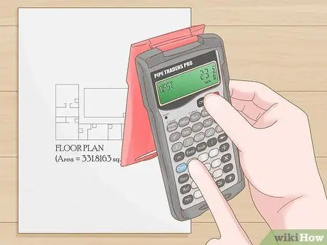
Step 6. Use a handyman calculator to add dimensions when determining spacing in your plan
This is a calculator that adds measurements in feet and inches, fractions, or metrics. Often an architect will not assign measurements to a specific plan item, from a basic guide such as “OBL” (Outside Building Line), so you should be able to add up the spacing for each feature, according to available measurements, to get the total distance.
One example, for example, when trying to find the center line of a bathroom wall to find the end of the drinking water pipe. You may have to add the distance in the OBL list to the middle cast wall, then the distance to the corridor wall, past the bedroom, to the bathroom wall you are aiming for. It might look like this: (11' 5”) + (5' 2") + (12' 4")= 28' 11
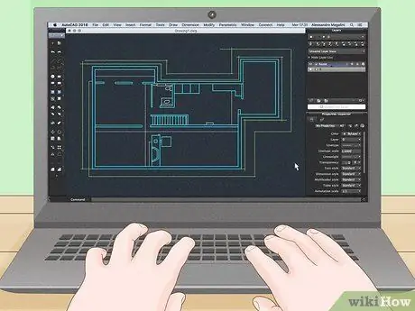
Step 7. Using a building plan with CAD (Computer Assisted Design)
If you have created a set of architectural plans in electronic form, such as a CD, to open the file you must have the original version of the "CAD" program used to create it. "AutoCAD" is indeed a popular professional design program, but it is very expensive, and designers usually include a "Viewer" program on a CD, which you can install onto your computer, in order to view the files in question. In this way, the floor plan pages can appear on the screen, but without the full program, you cannot manipulate design components or change drawings. However, most architectural firms know how to save CAD files and other files to PDF format, which are then emailed to you for you to open and view (though they cannot be changed, as Architects are responsible for maintaining the integrity of their work).

Step 8. Learn how to handle an architect's floor plan
These sets of documents are often very large, about 24" x 36", and for a full construction project they may contain dozens-if not hundreds of pages. Usually it is bound or bundled on the left edge, so that one of the pages can be torn off if necessary, or if the handling is not correct, such as being left in the sun until the ink is gone, or left in the rain to make the writing blurry and difficult to see.
All of these documents, if damaged, can cost hundreds of dollars to replace (US), so try to keep them right. Place it on a flat surface, wide and protected when opened and read

Step 9. Read the specifications
The specification sheet, usually printed and kept in a binder, contains a list of descriptions of the methods and materials used in the project, including test methods, quality control information, geotechnical data, and other information useful for constructing the project. However, there are also Architects who write specifications directly on the floor plan (to ensure that the specifications are not lost).
- Specifications are the Architect's way of marking quality standards, building materials, model numbers, and other project features. Even single-family homes have their own specifications. Specifications are usually laid out in numbered sections, Divisions 1 through 16. However these numbers have grown quite a lot in recent decades.
- Many Architects number paragraphs so that they can cross-check the actual diction of the specifications into the drawings, using paragraph number codes. This is quite effective in improving coordination on various occasions.
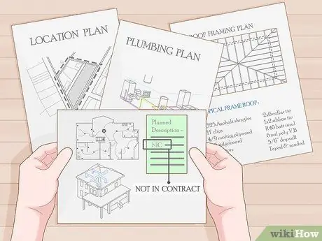
Step 10. Be aware of notes and symbols referring to “alternative bid items”, “Owner Choice Upgrades” and “attachments
"All of these signify a piece of work that is incorporated into the Architect's blueprint, but it doesn't have to be in the developer contract to be built, provided, or installed. "NIC" stands for Not In Contract, which means that a specific item that will be placed in a certain place by the building owner after the project is completed.
"OFCI" or "GFCI" (Owner Furnished, Contractor Installed = Owner Furnished, Contractor Installed, or Government Furnished, Contractor Installed = Government Furnished, Contractor Installed) indicates that the item was provided by the customer but was installed by the contractor. Read and understand all abbreviations used in your plan
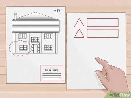
Step 11. Revision
Architects sometimes include attachments as well, in the form of changes made to the document after it has been released for auction. Many Architects intentionally leave a blank section, usually in the lower right corner of the plan, just above the page number, which is reserved as a Revision list, in case it is needed. Revisions are often numbered and embedded in a triangle, octagon, circle or other consistent symbol. To the right of each revision number is the date of the revision, then to the right is a brief description of the revision in question. In the drawing on the floor plan, the numbered symbol appears in the area where the revision was made, often with a "revision cloud", which is usually depicted as a series of curved lines stacked like a cartoon cloud, surrounding the revision area. This allows everyone to understand exactly what was changed. Also, the Architect usually accompanies this with an email containing a summary of the revisions in each attachment, which is sent simultaneously to the Owner and the registered bidder. After this, it is up to the bidders to communicate the changes to the existing information to the subcontractors and building materials providers.
Tips
- Be careful setting your floor plan as "original size", as many floor plans are presented in "full" and "half" original sizes, so you can scale distances with a full-size plan without having to scale through a ruler.
- If the plan is indeed half the original size, you'll need to halve your ruler readings. Note: most half-size plans are not declared as half-size or similar. Basically, in order for something to be considered a floor plan at half the original size, it is usually less than 24x18 (Arch C) paper size. Please note, sometimes this kind of floor plan is referred to as a half original size floor plan, even if it is made from 30x44 to 11x17, and thus makes it no longer actually half the original size.
- Look in house plan books or go online for ideas on the basic outlines, measurements, and appearance of architectural plans.
- Use the "triangle" calculation rule for the architect or engineer when scaling distances on a plan. All of this is structured in such a way and offers contact with the floor plan to allow for the exact positioning of the rules, while reducing the possibility of errors.
- When carrying out construction activities based on the architect's plans, keep a set of plans on site to note any changes, using red ink or pencil. These records, if any, are called "red line plans". Once a building is fully completed, this red line note is usually given to the drafter. These floor plans are called “Record Drawings” (RD) or “As Built”. This is a floor plan containing the red lines from the survey results directly on the site, which differs from the original set of plans (also called corrections).
Warning
- Make sure you get the necessary permits to construct a building before starting any construction. The building inspector can stop work on any project either unlicensed or not clearly displayed. In this case, a fine will be imposed.
- Be aware that the respective plumbing, electrical and mechanical plans do not always have enough space in the respective locations, so the installation of all components must be coordinated to avoid conflicts.
- If in doubt about measurements or other descriptions in the plan, immediately consult the architect who made it, rather than resorting to making mistakes that are difficult to correct later on.


