- Author Jason Gerald [email protected].
- Public 2024-01-15 08:07.
- Last modified 2025-01-23 12:04.
AutoCAD is computer software that allows people to create precise 2- and 3-dimensional drawings used in construction and manufacturing. You can use a Mac or Windows computer to run the latest version of AutoCAD. AutoCAD users can create scale drawings to build equipment, design infrastructure projects, design electrical circuits, and construct houses and other building structures. If you're not very familiar with AutoCAD, read this wikiHow to learn how it works and familiarize yourself with its basic functions and features.
Step
Method 1 of 2: Getting Started Using the Software
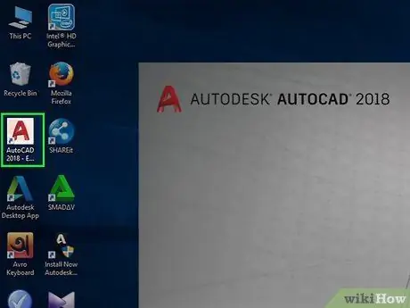
Step 1. Run AutoCAD
This application can be found in the Windows menu or the Applications folder on a Mac. If you don't have AutoCAD installed, download and install the application by visiting
Step 2. Browse to the Start screen
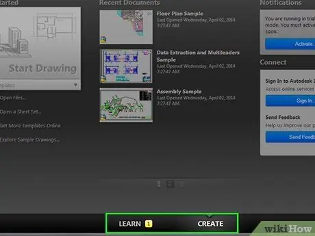
When running AutoCAD, there are 2 tabs at the bottom: LEARN and CREATE (this is the default tab). If you click on the LEARN tab, the screen will show a video tutorial for starting a drawing project. If you click on the CREATE tab, you'll see these areas:
- In the " Get Started " section on the left side, you can create a new project by selecting Start Drawing, open an existing project by selecting Open Files, or clicking the menu Templates to create a project from a template.
- If you have a new AutoCAD document you've worked on, it will appear in the Recent Documents section in the middle of the screen.
- If an update is available, you can see it in the Notifications area in the upper-right corner of the screen.
- You can also sign in to your A360 account by clicking Sign In in the lower right corner.
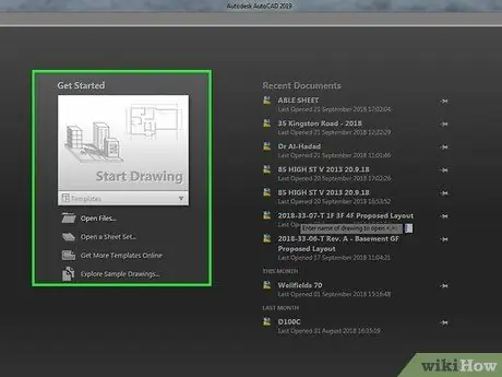
Step 3. Click Start Drawing or open an existing file
If you want to create a new project from a template, select the desired template.
If the option you want doesn't appear, click File, then select New to create a new project.
Step 4. Familiarize yourself with the layout of his workspace
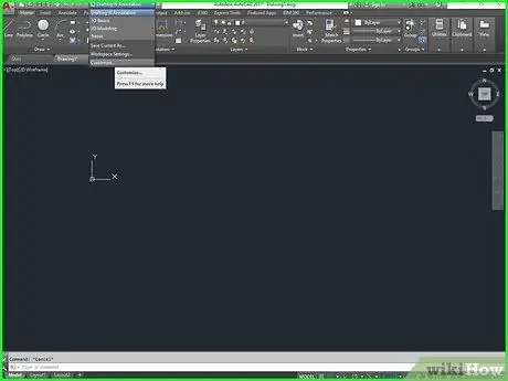
After opening the image creation screen, familiarize yourself with the location of each menu and tool:
- The drawing area is the part of the workspace that has a latticed background. There are 2 tabs in the upper left corner of this area: one is for the current drawing (with titles such as "Drawing1 " and so on), and the other is a tab for returning to the screen. Start. When you open multiple images at once, each image will have its own tab above the drawing area.
- The Y-axis is shown in green on the left side of the drawing area, while the X-axis is a red line along the bottom.
- The viewcube is a box around which there is a directional compass. This can be used to adjust the perspective when you create 3D images.
-
The ribbon toolbar at the top of the drawing area contains various tools placed in a series of tabs (Home, Insert, Annotate, etc).
Click tab View at the top if you want to show and hide tools and features in the workspace.
- The "Type a command" area is at the bottom, which is used to type commands and run tool functions once you're familiar with the program.
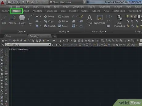
Step 5. Click the Home tab at the top left of the AutoCAD screen
The drawing tools are placed in the " Draw " area to the left of the ribbon toolbar.
- Hover the mouse over one of the tools to display more information about the function of the tool, and instructions for further assistance on how to use it.
- When drawing with a tool, near the cursor will display useful measurements, such as lengths and angles.
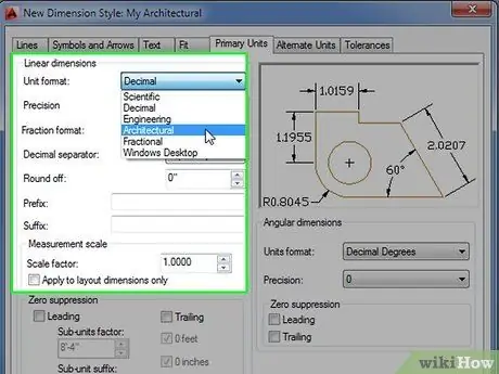
Step 6. Set the default measurement format
If you want to change the display of length, scale, or angle measurements, type units in the command prompt and press Enter or Return to open the Drawing Units panel. For example, if the measurement is shown in microns, and you need the measurement in meters, you can change it here at any time.
Method 2 of 2: Drawing in AutoCAD
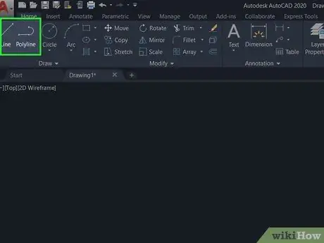
Step 1. Draw a line by clicking the Line tool or polyline.
These two tools are in the top left corner. Lines are used to draw individual line segments, and Polylines are used to create an object from a series of line segments. Perform these steps to create a line:
- Click the mouse at the point where you want to start the line segment.
- Move the mouse to where you want to use the end of the segment, then click the mouse at the end point of the line. If using the Line tool, this will finish creating the segment/line you created.
- If using Polyline, move the mouse again and click to continue creating the segment. When finished, stop the drawing process by pressing the button Esc.
- If you need to use exact measurements on the created segment (this applies to any tool), type the desired measurement into the box near the cursor, instead of clicking the point of the last segment. When pressing the button Enter or Return, the end point will be placed at the distance you have typed in.
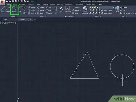
Step 2. Draw a circle by clicking the Circle tool
It's located to the right of the Polyline in the toolbar. Draw a circle using these steps:
- Click a point in the drawing area that will be used as the center of the circle.
- Drag the mouse outwards, then click to select a radius.
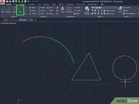
Step 3. Draw a curved line by clicking the Arc tool
It's to the right of Circle in the toolbar. Draw a curved line by doing these steps:
- Click the mouse at the starting point.
- Move the mouse and click where you want to end the segment.
- Move the mouse in the direction of the desired curve, then click the mouse to curve the line.
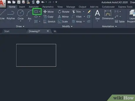
Step 4. Create a rectangle by clicking the Rectangle tool
Using the Rectangle tool is quite easy, click on the starting point (which will be one of the corners of the rectangle), then drag the mouse until you get the rectangle size you want. Click the mouse to place the rectangle.
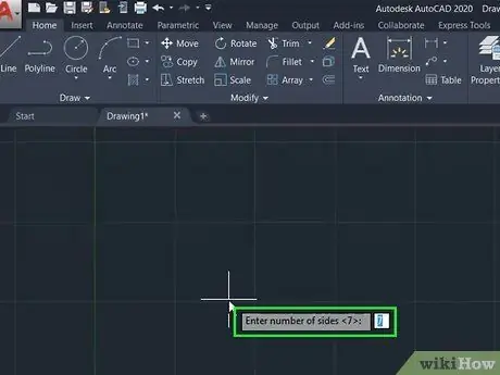
Step 5. Click the Polygon tool to create a multi-sided image
How to do it:
- Move the cursor to the drawing area-you will see a box with the words "Enter the number of sides". Enter the desired size number, then press the button Return or Enter.
- Click the location to be the center point of the image.
- Move the mouse until the image reaches the size you want, then click the mouse to place the image.
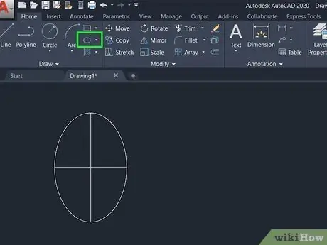
Step 6. Make an oval shape by clicking the Ellipse tool
You have to place 3 dots to create an ellipse. How to do it:
- Click the center point you want.
- Move the mouse until it's the size you want, then click the second point.
- Move the mouse to form an ellipse, then click to place the image.
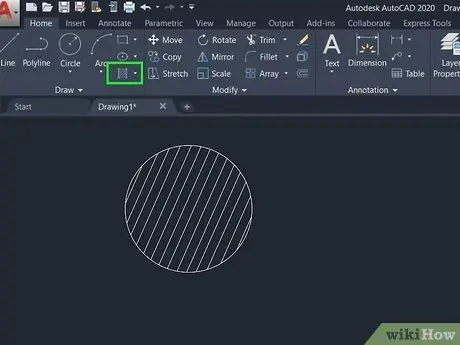
Step 7. Fill an image shape with a pattern using the Hatch tool
It's a box-shaped tool in the lower-right corner of the Draw panel in the toolbar. Click the tool, then click an image shape to fill in. You can select a fill in the form of a pattern or solid which is displayed in the " Pattern " panel that appears in the toolbar when Hatch is activated.
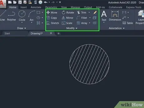
Step 8. Edit a shape using the tools present in the " Modify " panel
If you simply click on a line or shape without selecting the tool first, the anchor point will be displayed. These anchor points can be dragged to change a shape if you want. There are many modifications that can be made:
- Click Move to move a shape or line. After clicking a tool, click the object you want to move, then drag it to where you want it. You can select multiple objects at once to be moved in a group.
- Click Rotate, then click a shape to rotate it clockwise or vice versa. Use tools Mirror to flip the image.
- Click Scale, then click a shape to resize it. Check out the wikiHow article on how to scale an image in AutoCad if you want to learn more about scaling.
- choose Stretch to resize an image by stretching it, not with the scale tool.
- Choose one of the Array tools (Rectangular Array, Polar Array, or Path Array) to duplicate (do an array) the selected object.
- Tool Trim can be used to cut a segment or edge of an object that overrides the boundary of another object, turning it into a single object.
- use Fillet and chamfer to create curved and sharp corners by crossing the 2 selected sides.
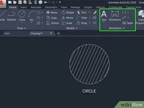
Step 9. Add text and tables by clicking the Annotate tab
This tab is next to the "Insert" tab at the top. It can be used to create text boxes, add tables containing multiple rows and/or columns, and so on.
- If you want to switch between text types, select Single Line or Multi-Line which is at the top left of the ribbon toolbar.
- All added text also functions as a single, moveable object.
- There is a "Dimensions" panel within this tab that can be used to specify the dimensions of a line or shape.
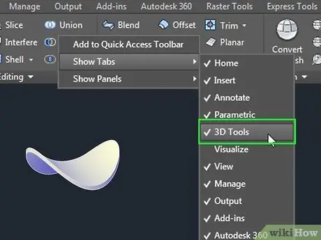
Step 10. Create a 3D object
You can use 2 ways to switch to 3D view. First, drag the Viewcube in the upper right corner of the drawing area in any direction. The second way, click the icon Orbit in the right pane (the icon is a circle with an arrow pointing up).
- Click tab 3D Tools at the top to open the 3D design editing tools. If this tab doesn't exist, right-click the empty space next to the last tab above the ribbon toolbar, go to Show tabs, then select 3D Tools.
- Click the down arrow under " Box " in the " Modeling " pane of the toolbar view, then select the 3D object you want to create (eg. Cone [cone], Sphere [ball], or Pyramid [pyramid]). The drawing method is the same as when you create a regular 2D drawing, but there will be other axes (blue lines) to deal with.
- The shape will be displayed as a 3D line drawing, not as a volume. You can change it by clicking 2D Wireframe which is in the upper left corner of the drawing area, then choose another view, for example realistic, Shaded, or X-ray.
- If you want to convert a 2D object to a 3D object, use the tools Extrude to add depth, and/or tools Revolve to rotate an object around an axis.
- You can modify 3D objects just like 2D objects. The trick is to click on an object to bring up a blue node (connection point that connects lines/images) that you can drag, then move it to where you want it.
- The " Solid Editing " and " Surfaces " panes contain advanced editing tools for creating and editing complex objects.
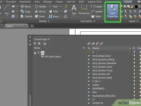
Step 11. Place the image on another layer
When creating complex drawings, it's a good idea to place each part onto a different layer, which can be edited, hidden, viewed, and rearranged. Here are some basic things you need to know to create layers:
- On tab Home, click icon Layer Properties in the " Layers " panel to bring up the Layer Properties panel. This will bring up all the layers and what can be done with them.
- Click on the 3 sheet of paper icon with the red and yellow circles on the left side (it's the first icon at the top of the Layer Properties panel) to create and name a new layer. Now you have 2 layers in the panel.
- Select a layer by double-clicking on it. The layer that has a checkmark is the layer that is currently displayed.
- Hide or show layers by clicking on the lightbulb on the layer. If you're dealing with very large files, use the sun-shaped icon to freeze the layer instead of hiding it.
- Use a padlock-shaped icon to prevent layers from being accidentally edited. This will lock the layer.
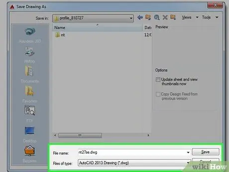
Step 12. Save the image you created
Save your work by clicking the menu A in the upper left corner, clicking Save As, and choose Drawing. Your drawing will be saved as a DWG file, which is the default format for AutoCAD.
- Now that you've mastered the basics of AutoCAD, now try to create an L-shaped staircase or multilevel pyramid.
- If you're already proficient with AutoCAD, you'll be able to turn lines into surfaces, from surfaces into 3D solids, add realistic representations of materials, and manipulate light and shadow.


