- Author Jason Gerald gerald@how-what-advice.com.
- Public 2024-01-19 22:11.
- Last modified 2025-01-23 12:04.
A multimeter, also known as a volt-ohm meter or VOM, is a device for measuring resistance, voltage, and current in an electrical circuit. Can also be used to check diodes and continuity. Multimeters are small, lightweight, and run on batteries. It can inspect a wide variety of electrical components under many conditions, making it an indispensable tool for anyone who needs to inspect and repair electrical circuits.
Step
Method 1 of 5: Measuring Voltage
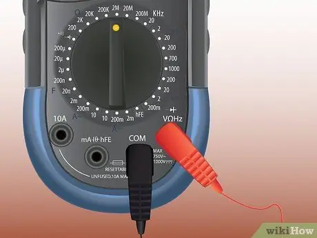
Step 1. Connect the multimeter to the circuit
Insert the black probe into the common terminal and the red probe into the voltage and resistance measuring terminal.
Both AC and DC voltages are measured with the test lead wires in this step
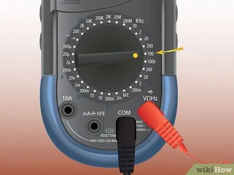
Step 2. Set the multimeter to the voltage being measured
You can measure DC voltage (direct current), millivolt DC, or AC voltage (alternating current). If your multimeter has an automatic voltage range function, you do not need to select the voltage being measured.
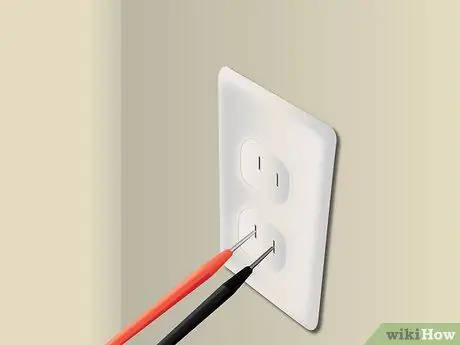
Step 3. Measure the AC voltage by placing the probe on the component
You don't need to pay attention to the polarity.
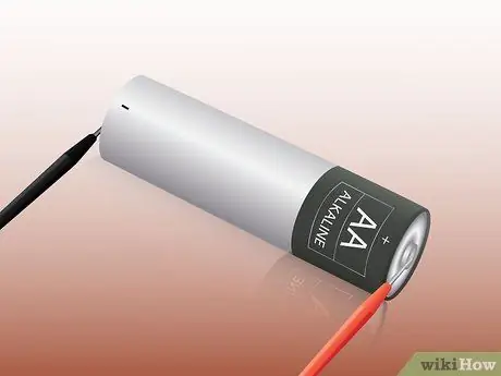
Step 4. Pay attention to the polarity if you are measuring DC voltage or millivolts
Place the black probe on the negative pole of the component and the red probe on the positive pole.
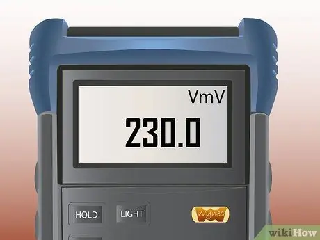
Step 5. Read the displayed numbers, paying attention to the units
If you want, you can use the touch-hold feature to keep displaying the measurement results after you unplug the probe. The multimeter will flash whenever a new voltage is detected
Method 2 of 5: Measuring Current
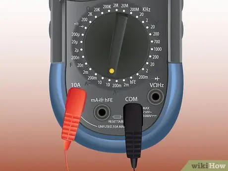
Step 1. Choose either the 10 ampere gauge or the 300 milliampere (mA) gauge
If you are unsure of the current, start with the 10 ampere terminal until you are sure the current is less than 300 milliamperes.
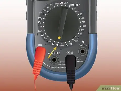
Step 2. Set the multimeter to measure the current
This mode is marked with the letter A.
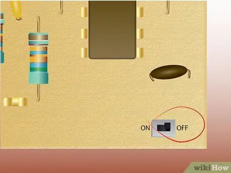
Step 3. Turn off the power to the circuit
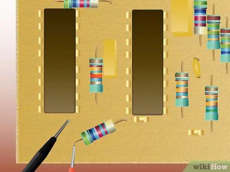
Step 4. Disconnect the circuit
To measure current, you must connect the multimeter in series. Place a probe on each end of the piece, paying attention to the polarity (black probe on the negative pole, red probe on the positive pole).
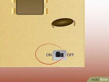
Step 5. Turn on the power
The current will pass through the circuit, enter the red probe and through the multimeter, then exit the black probe and enter the circuit again.
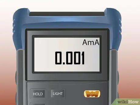
Step 6. Read the displayed numbers, remembering whether you are measuring in amperes or milliamperes
You can use the touch-hold feature if you want.
Method 3 of 5: Measuring Barriers
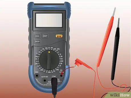
Step 1. Connect the multimeter to the circuit
Insert the black probe into the common terminal and the red probe into the voltage and resistance measuring terminal. This terminal can also be used to check diodes.
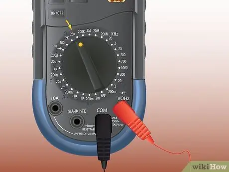
Step 2. Turn the selector knob to adjust the resistance
This mode is indicated by the Greek letter Omega, which stands for ohm, the unit of measurement for resistance.
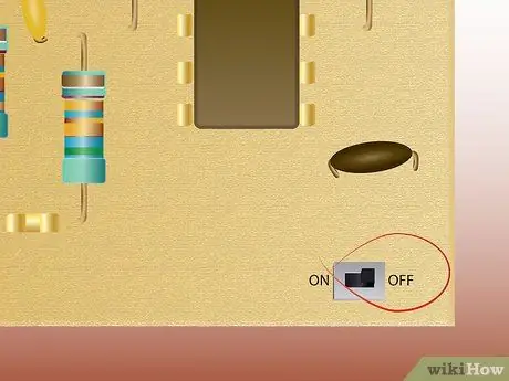
Step 3. Turn off the power to the circuit
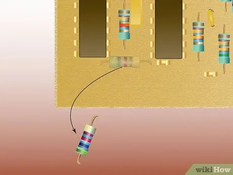
Step 4. Remove the resistor you want to measure
If you leave the resistor in the circuit, the measurement results may not be accurate.
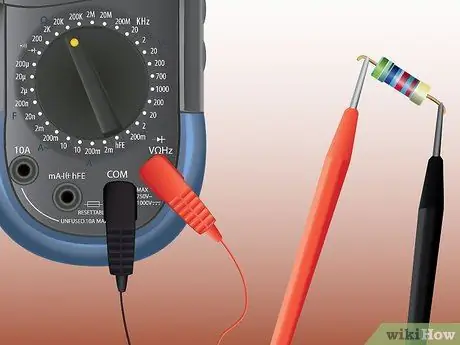
Step 5. Touch the probe tip to each end of the resistor
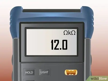
Step 6. Read the displayed numbers, paying attention to the units
A measurement of 10 can denote 10 ohms, 10 kilo-ohms or 10 mega-ohms.
Method 4 of 5: Checking Diodes
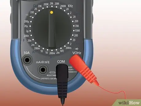
Step 1. Insert the black probe into the common terminal and the red probe into the terminal to measure resistance, voltage, or check the diode
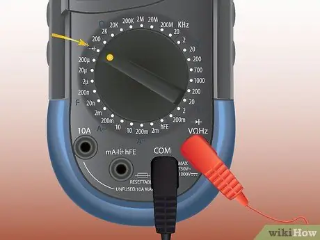
Step 2. Use the selector knob to select the diode check function
This mode is indicated by a symbol representing the diode, which is an arrow pointing to a vertical line.
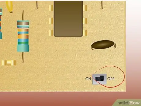
Step 3. Turn off the power to the circuit

Step 4. Check forward bias
Place the red probe on the positive pole of the diode and the black probe on the negative pole. If you get a measurement result of less than 1 but more than 0, the forward bias is fine.

Step 5. Turn the investigator over to check for reverse bias
If the measurement result shows "OL" (overload), this indicates the reverse bias is in good condition.
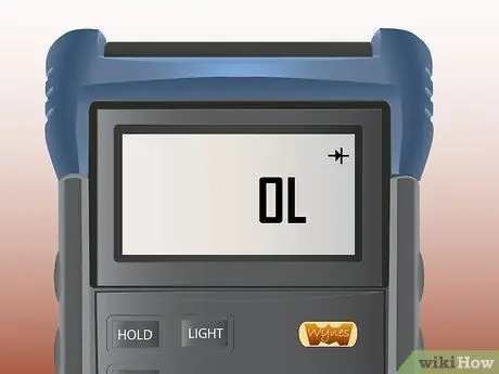
Step 6. A reading of "OL" or 0 when checking forward bias, and 0 when checking reverse bias indicates a bad diode condition
Some multimeters will flash when the measurement result is less than 1. This does not necessarily indicate the diode is in good condition, as a faulty diode will also result in a flashing display
Method 5 of 5: Measuring Continuity
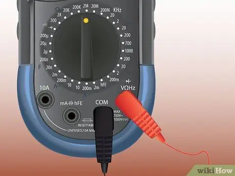
Step 1. Insert the black probe into the common terminal and the red probe into the voltage and resistance measuring terminal
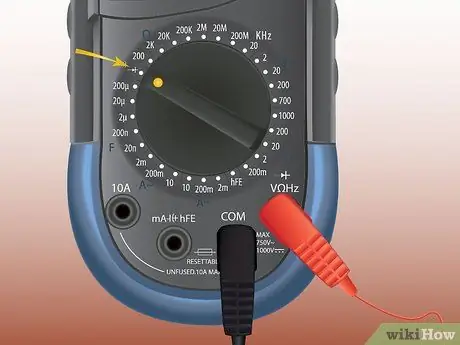
Step 2. Set the multimeter to the same setting used to check the diode
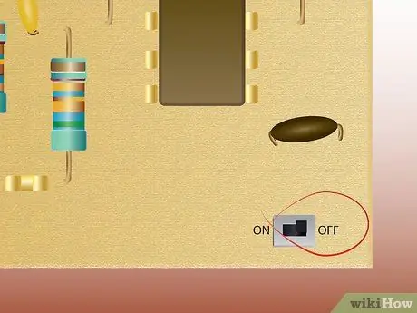
Step 3. Turn off the power to the circuit
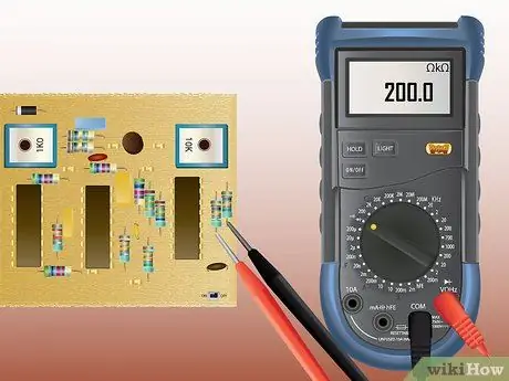
Step 4. Place the probe on each pole of the circuit being examined
You don't need to pay attention to the polarity. A reading of less than 210 ohms indicates continuity in good condition.


