- Author Jason Gerald [email protected].
- Public 2023-12-16 10:50.
- Last modified 2025-01-23 12:04.
Have you ever lost your WiFi antenna? Most antennas can be removed from the WiFi card, making them easy to lose. Using a few household items, you can create an effective replacement antenna, which you can use until you can buy a replacement. If you have coverage issues, you can build your own directional antenna, which can significantly increase the distance from your wireless connection.
Step
Method 1 of 2: Making Antenna Replacement from a Paperclip
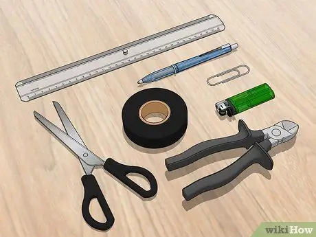
Step 1. Gather your materials and tools
To make an antenna, you'll need a large paper clip, an empty Bic ballpoint pen and a roll of electrical insulation. You will also need a ruler, scissors and a lighter.
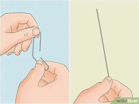
Step 2. Align the paper clip
Unfold the paper clip into a straight piece of iron.
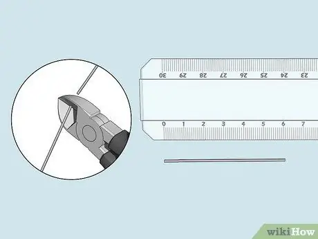
Step 3. Measure and cut the paper clip
For the best signal, your paper clip should be 61mm long. Try to get as close to this size as possible to make the most effective antenna possible.
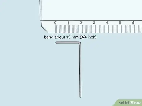
Step 4. Bend the paper clip
Bend the paper clip on one side, at about 19 mm (3/4 inch) in size, forming an angle of 90°. This will be the part that goes into the WiFi antenna port.
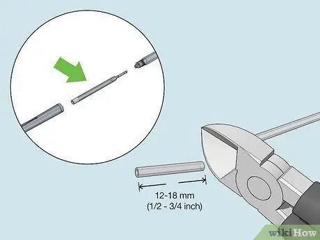
Step 5. Remove the ink cartridge from the ballpoint pen
Since you will be clipping the ink cartridge, it is best to use a ballpoint pen that is not being used for writing anymore. Clip about 12-18 mm (1/2 inch to 3/4 inch) from the tube that contains the ink. This may get dirty, so be sure to hold the tube a little further away when you cut it. Cut the tube over a surface that won't stain you.
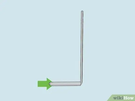
Step 6. Slide the tube into the bent part of the paper clip
Place the cut tube onto the end of the paper clip. Make sure that the tube extends beyond the end of the paper clip by about 1.5 mm (1/16 inch).
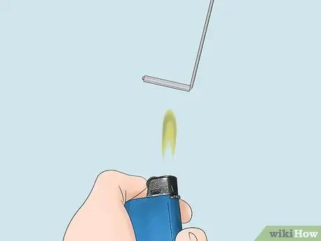
Step 7. Shrink the tube with a lighter
Take a lighter or other heat source and SLOWLY heat the tube in the paper clip. This will shrink the tube and tighten the connection to the paper clip.
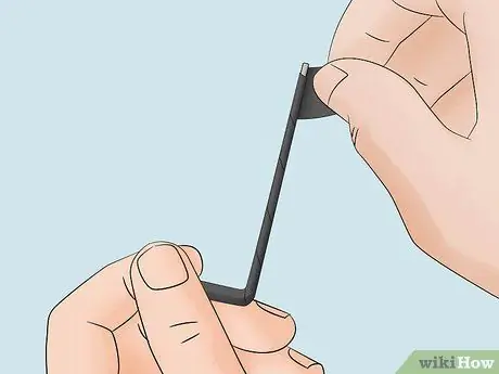
Step 8. Isolate the antenna
Wrap the paper clip with electrical insulation to avoid excessive interference with the wireless signal.
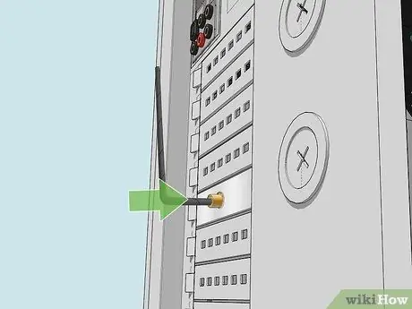
Step 9. Insert the paper clip into the antenna port
Insert the 'tube' end of the paperclip into the antenna connector making sure that the connector pins and the paperclip are pressed together and pressed against the inside of the tube. If you can make them overlap, then the signal will be even better.
Method 2 of 2: Creating a Steering Antenna
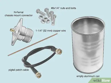
Step 1. Gather your materials and tools
To make this directional antenna, you will need an N-Female connector embedded into the chassis, four #6x1/4" bolts and nuts, 32 mm (1 1/4") copper wire, pigtail patch cord and an aluminum tin. empty.
- You will also need a drill, a soldering iron and a screwdriver to match the bolts.
- A pigtail cable is a patch cord with connectors on both ends of the cord.
- Aluminum cans should have one side open and the other side with a metal base.
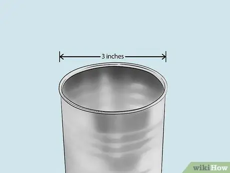
Step 2. Measure the diameter of the can
The diameter of the can determines where the connector will be embedded. Your can must be at least 7.6 cm (3 inches) wide, but can also be 15.2 cm (6 inches) wide.
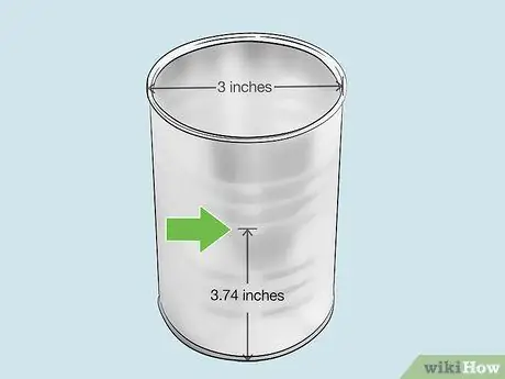
Step 3. Mark the point where the connector will be embedded
Measure from the bottom of the can and mark the outside where the connector will be. Size will vary depending on the diameter of the can. This measure will determine the maximum signal strength. Below are some common sizes:
- 7.6 cm (3 inches) - 9.5 cm (3.74 inches)
- 8.9 cm (3.5 inches) - 5.25 cm (2.07 inches)
- 15.2 cm (6 inches) - 3.5 cm (1.38 inches)
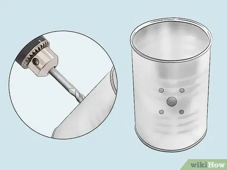
Step 4. Make a hole in the inside of the can
Use a drill bit that is the same size as the small side of the N-Female connector to drill a hole that you measured earlier. You can also use a hammer and nails if you don't have a drill.
If your N-Female connector has screw holes, drill smaller holes around the larger holes to allow you to insert them using nuts and bolts
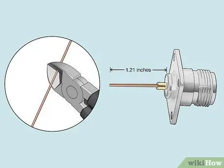
Step 5. Measure and cut the wire
Take your copper wire and place it in line with the metal connector on the side of the small N-Female connector. The small brass tubing and the length of the cable should all reach 3.07 cm (1.2i in) when placed in an inline position. Try to physically approach this size as closely as possible, to get the best possible connection.
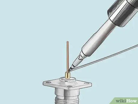
Step 6. Solder the copper wire to the end of the small N-Female connector
Use solder to attach the wire to the brass tube on the back of the N-Female connector. This will create a probe. Check out this guide for details on how to solder. The wire should protrude from the connector.
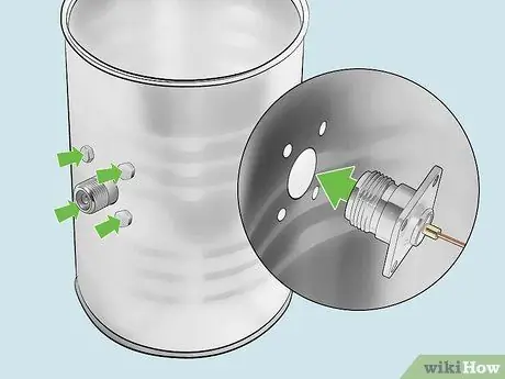
Step 7. Secure the probe in the can
Once the solder has cooled, embed the probe into the can with the wires on the inside and the screw connectors on the outside. Use nuts and bolts to secure the probe to the can.
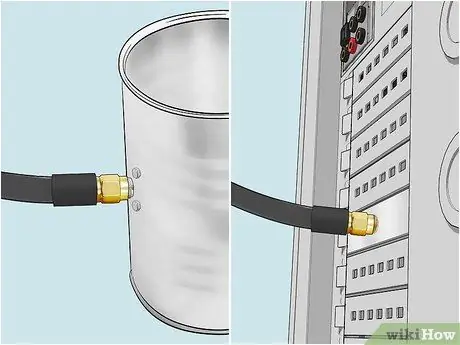
Step 8. Connect the can to the wireless card using a pigtail cable
Screw the pigtail cable into the implanted probe, and then connect the other end to your wireless card's antenna connector.
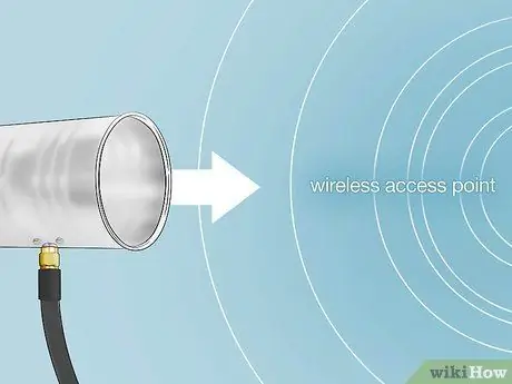
Step 9. Point the can at the physical location of the access point
The can should be pointed directly at the wireless access point. You can attach it to a camera tripod with a zip tie for easy direction.


