- Author Jason Gerald gerald@how-what-advice.com.
- Public 2023-12-16 10:50.
- Last modified 2025-01-23 12:04.
A computer power supply costs around US$30, but for a laboratory power supply, you can be charged $100 or more! By changing to a cheap (free) ATX power supply, which can be found in every discarded computer, you can get a phenomenal laboratory power supply, with a large output current, short circuit protection and fairly tight voltage regulation on the 5V line. In most power supply units (PSU), the other voltages are not regulated.
Step

Step 1. Look for an ATX computer power supply online or at your local computer store, or disassemble an old computer and remove the power supply from its case
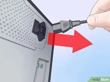
Step 2. Unplug the power cord from the power supply and turn off the switch on the back (if available)
At the same time, make sure your feet don't hit the ground directly, so any residual stress won't run through you to the ground.
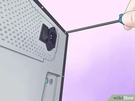
Step 3. Remove the screws that secure the power supply to the computer case and remove the power supply
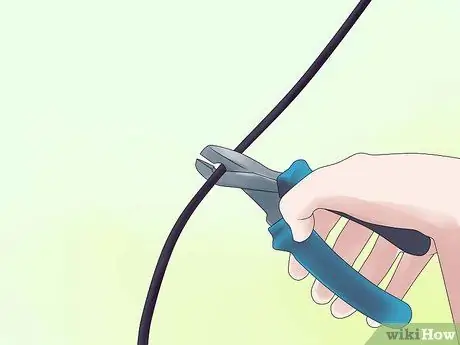
Step 4. Cut the connectors (leaving the wires on the connectors a few inches so you can use them later for other projects)
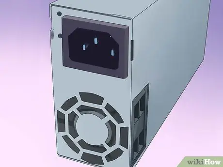
Step 5. Discharge any remaining electrical current in the power supply by leaving it unplugged for a few days
Some have suggested putting a 10 ohm resistor between the black and red wires (from the power lead on the output side), but this is only guaranteed to drain the low voltage capacitor at the output - harmless to begin with! This can leave high-voltage capacitors charged, potentially making them dangerous or even deadly.
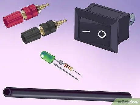
Step 6. Gather the items you need:
terminals, an LED with a current-limiting resistor, a switch (optional), a resistor (10 ohms, 10W or greater power, see Tips), and a heat-shrinkable tube.
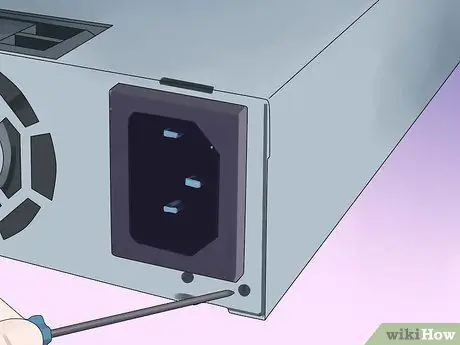
Step 7. Open the power supply unit by removing the screw that connects the top and bottom of the PSU case

Step 8. Gather wires of the same color
If you have a cable not listed here (brown, etc.), take a look at Tips. The color codes for the wires are: Red = +5V, Black = Ground (0V), White = -5V, Yellow = +12V, Blue = -12V, Orange = +3.3V, Purple = +5V Standby (not used), Gray = power on (output) and Green = PS_ON# (turn on DC by grounding it).
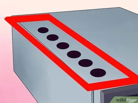
Step 9. Make a hole by drilling it in the free area of the power supply case, marking the center of the hole by tapping the nail with a hammer
Use the Dremel to drill the initial holes, followed by a hole enlarger, until they are the right size, testing the size by attaching the terminals. Make holes at once by drilling them for the ON LED power light and Power switch (optional).
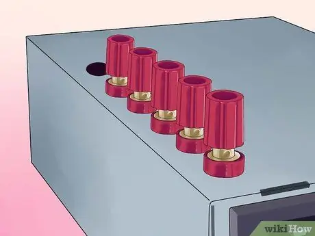
Step 10. Screw the terminals into their respective holes and tighten the nuts on the backs
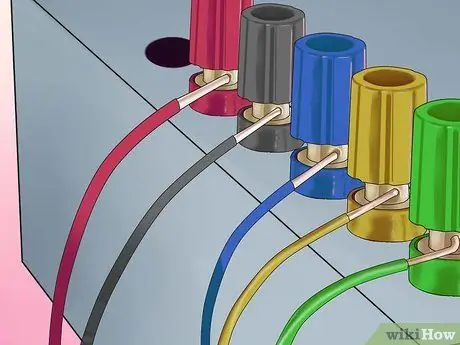
Step 11. Connect all the existing parts
- Connect one of the red wires to the resistor and all the remaining red wires to the red terminals;
- Connect one of the black wires to the other end of the resistor, one to the LED cathode (the shorter end), one to the DC-On switch and all remaining black wires to the black terminal;
- Connect the white wire to the -5V terminal, the yellow to the +12V terminal, the blue to the -12V terminal, the gray to the resistor (330 ohms) and attach it to the LED anode (longer end);
- Note that it is likely that some power supplies have a gray or brown wire to represent "power good"/"power ok" (most PSUs have a small orange wire used to detect -- 3.3V- and this wire is usually plugged in. on the connector with the other orange wire. Make sure this wire is connected to the other orange wire, otherwise your laboratory power supply won't stay on). This wire must be connected to either the orange wire (+3, 3V) or the red wire (+5V) for the power supply to work. When in doubt, try a lower voltage first (+3, 3V). If a power supply doesn't meet ATX or AT requirements, it likely has its own color scheme. If yours looks different from the pictures shown here, make sure you refer to the position of the cable connected to the AT/ATX connector, not the color.
- Connect the green wire to the other terminal on the switch.
- Make sure that the soldered ends are insulated with heat shrinkable tubing.
- Arrange the cables with electrical insulation or a zip-tie.
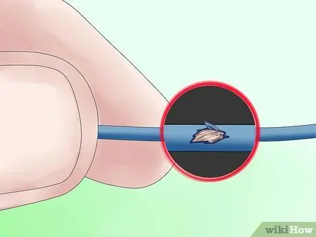
Step 12. Check for loose joints by gently tugging
Check for unwrapped wires and cover them to prevent short circuits. Drop a little super glue to attach the LED to the hole. Put the cover back on.

Step 13. Plug the power cord into the back of the power supply and into a power outlet
Turn on the mains bypass switch on the PSU, if available. Check if the LED light is on. If not, then turn on the switch you placed on the front. Plug a 12V bulb into a different socket to see if the PSU is working, as well as check with a digital voltmeter. Make sure you don't forget any cables. It should look good and work great!
Tips
- Option: You don't need an extra switch, just connect the green and black wires together. The PSU will be controlled by a rear switch, if available. You also don't need an LED light, just ignore the gray wire. Cut it short and isolate it from the rest.
- If you don't want to simultaneously solder nine wires to the terminals (as is the case with the ground wire), you can cut them on the PCB. 1-3 should suffice. This includes cutting cables that are planned to never be used.
- Feel free to add some pizzazz to the dull gray box.
- You can use the output of your 12V power supply as a car battery charger! However, be careful: if your car battery is too discharged, the power supply short circuit protection will be triggered. In this case, it is preferable to place a 10 Ohm, 10/20 Watt resistor in series with the 12V output, so as not to overload the power supply. Once the car battery is close to 12V charging (you can use a tester to confirm that), you can remove the resistor, to charge the rest of the car battery. This can save you money if your car has an old battery, if it won't start in winter or if you accidentally leave your lights or radio on for hours on end.
- You can also convert it to a variable voltage power supply - but this is in another article (hint: Use an IC 317 with transistors).
- You can add a 3.3 volt output (as used to power devices that run on 3V batteries) to the power supply by attaching the orange wire to the terminals (make sure the brown wire stays connected to the orange wire). Be careful though, as they share the same 5 volt power output and thus the two outputs should not exceed that total power.
- The +5VSB line is +5V standby (as works for the motherboard power button, Wake on LAN, etc.). This line typically provides 500-1000 mA of current, even when the main DC output is in the "off" position. It may be useful to light an LED, as an indication that the power is on.
- The voltage that can be output from this unit is 24v (+12, -12), 17v (+5, -12), 12v (+12, GND), 10v (+5, -5), 7v (+12, 5), 5v (+5, GND), which should be sufficient for most electrical tests. Many ATX power supplies with a 24 pin connector for the motherboard do not provide the -5V pin. Look for an ATX power supply with a 20 pin connector, a 20+4 pin connector or an AT power supply if you need -5V.
- The ATX power supply is a switch mode power supply (info at https://en.wikipedia.org/wiki/Switched_mode_power_supply); they must always have a load to function properly. The existence of a resistor is to "waste" energy, which will release heat; therefore, the resistor must be mounted on a metal wall for sufficient cooling (you can also use a cooling iron to embed your resistor, make sure the cooling iron does not cause a short circuit). If you're always going to have something plugged into the power supply while it's on, it's OK to leave out the resistor. You can also consider using a 12v switch that has a light, which will act as the load needed to turn on the power supply.
- To get more space, you can install the fan outside the PSU case.
- Some power supplies also require gray and green wires to connect to each other in order to function.
- If you're not sure about the power supply, test it on your computer first before you take it out. Is the computer on? Is the PSU fan working? You can insert your voltmeter needle into the extra plug (for disk drives). It should read close to 5V (between the red and black wires). A power supply that you have removed, will likely appear dead because it has no load on its output and the switched output may not be grounded (green wire).
- You can take advantage of the hole previously used by the power supply cable, to attach the cigarette lighter connector. That way, you can connect your car equipment to the power supply.
- If you HAVE a detection wire for 3, 3v., connect the 3, 3v section. from the power supply using a voltage of 3, 3v. as the opposite voltage to, say 12v. to get 8.7v., won't work. You will read 8, 7 v. with a volt meter, but when you overload that 8.7v circuit, it's likely that the power supply will go into protection mode and turn off the power supply entirely.
- If you're not afraid to do some soldering, you can replace the 10w resistor with a cooling fan, which is originally located inside the PSU, though be careful with polarity - match the red and black wires to each other.
- The -5v rail has been removed from the ATX specification and is not available on all ATX power supplies.
- Chances are you'll have to drill a slightly larger hole.
- If the power supply is not working, where the LED light is not on, check if the fan is running. If the fan in the power supply is on, then the LED wires may have been connected incorrectly (possibly the positive and negative ends of the LEDs have been swapped). Open the power supply case and flip the purple or gray wire around the LED (make sure you don't miss the LED resistor).
- Some newer power supplies will have a "voltage detection" wire that must be connected to the actual voltage lead for proper operation. In the main power cord set (which consists of 20 wires), you should have four red wires and three orange wires. If you only have two or less orange wires, you should also have brown wires that must be connected to the orange wire. If you only have three red wires, the other wire (sometimes pink) should be connected to them.
- The fan in a power supply can make quite loud noises; it is designed to cool a power supply as well as a relatively overloaded computer. It is possible to simply clamp the fan in, but this is not a good idea. A way to get around this is to cut the red wire leading to the fan (12V) and connect it to the red wire coming out of the power supply (5V). Your fan will now run significantly slower and thus quieter, but still provide cooling. If you're planning to draw a lot of current from the power supply, this might be a bad idea, consider it and see how hot it gets. You can also remove the standard fan and replace it with a quieter model (there will be some soldering to do).
- For use with items with high starting loads, such as 12v refrigerators with capacitors, connect a suitable 12v battery to avoid overloading the power supply.
Warning
- Do not touch the path leading to the capacitor. Capacitors are cylinders encased in a thin plastic sheath, with an exposed metal part at the top, usually with a + or K sign. Solid-state capacitors are shorter, have a slightly wider diameter and do not have a plastic casing. They retain power like batteries, but unlike batteries, they can drain power very quickly. Even if you run out of power, you should avoid touching any point on the board unless necessary. Use a probe to connect anything you might touch ground to before starting work.
- If you suspect the power supply is faulty, do not use it! If it has been damaged, then the protection circuit is probably not working. Normally, a protection circuit will slowly deplete a high-voltage capacitor - but if the power supply is connected to 240V while it was previously set at 120V (for example), then the protection circuit may have been destroyed. If so, it is likely that the power supply will not turn off when it is overloaded or when it starts to fail.
- Make sure that you drain the capacitor. Plug in the power supply, turn it on (connect the Power cable, which is green, to ground), then unplug the power supply until the fan stops spinning.
- When drilling the metal casing, make sure that no metal debris gets inside the PSU. This could cause a short circuit, which in turn could cause a fire, extreme heat or a dangerous electrical surge at one of the outputs, which would damage your new laboratory power supply that you have worked so hard to build.
- Don't remove the circuit board unless you have to. The traces and solder on the bottom still have a high voltage if you don't leave the PSU on long enough. If you must remove it, use a measuring device to check the voltage on the pins of the largest capacitors. When you replace the board, make sure that the plastic sheet is back under it.
- A computer power supply is good enough for testing purposes or for running simple electronics (eg battery chargers, soldering irons), but will never produce the same power as a good laboratory power supply. So, if you intend to use your power supply for more than just testing, buy a good laboratory power supply. There is a reason why they cost so much.
- Voltage line can kill (anything above 30 milliamps/volt can kill you in a matter of time, if it somehow penetrates your skin) and at least delivers a painful shock. Make sure that you have unplugged the power cord before making any changes and that it has drained the capacitor as described in the steps above. When in doubt, use a multi tester.
- The resulting power supply will provide high output power. This may happen if you create an arc at the low-voltage output or fry the circuit you are working on, if you make a mistake. Laboratory PSUs have adjustable voltage limits for a reason.
- The original article states that make sure you are grounded. That is untrue and dangerous. Make sure you don't hit the ground directly when working on the power supply, so electrical power won't flow through you to the ground.
- This of course will void any type of warranty.
- Only a power supply technician should attempt to do this.


