- Author Jason Gerald [email protected].
- Public 2023-12-16 10:50.
- Last modified 2025-01-23 12:04.
A 3-way light switch lets you control the lights from two different points. While the 3-way switch is one of the most difficult electrical circuits to understand, it is also one of the most useful. Read Step 1 for one of the easiest ways to install a 3-way light switch.
Step
Part 1 of 3: Installing the 3-Way Switch
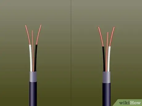
Step 1. Choose the right wire size
If coming from an electrical panel or fuse box, copper wire #12 is the minimum size for connecting to a circuit breaker or 20 amp fuse; copper wire #14 is the minimum size for connecting to a 15 amp circuit breaker or fuse (aluminum wire in circuits for these capacities was banned many years ago).
The size of all wires in any circuit “must” be the same. When drawing power from an electrical socket or other nearby circuit device, the new electrical wire must be of the same size as the electrical wire supplying the socket
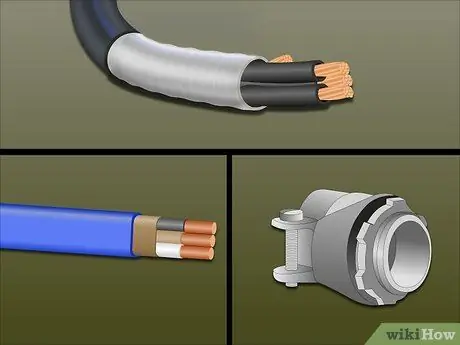
Step 2. Choose the right type of cable
The power supply or feed cable should be a “2 wire” (or conductor) “plus” one ground wire. See below for a description and use of the common types of cables.
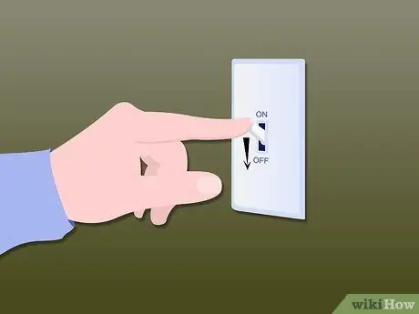
Step 3. Turn off the power source
This is a very important step. Please don't skip this step.
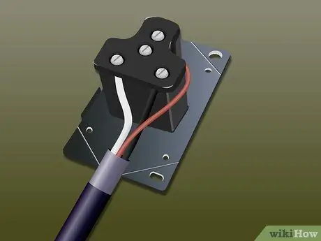
Step 4. Install a 2-wire cable between power sources (socket box, electrical panel, etc
) and the first toggle box. Leave 20.3 - 25.4 cm of wire in both boxes (mains source and first switch) before cutting wires for easy connection to switch and power source. Connect the ground wire to the circuit ground wire with a wirenut or other suitable connector (see how to connect the electric wire). The ground wire should be connected to the neutral terminal bar. Finally, connect the black wire to a power source or circuit breaker or fuse and the white wire to a neutral source or neutral terminal bar on the electrical panel.
- If equipped with a separate ground bar, instead of being connected to the neutral terminal bar, the ground wire can be connected to the ground terminal bar. However, if all existing ground wires are connected to one bar and all existing white wires are connected to different bars, it is necessary to keep the ground and neutral connections separate.
- “Never” connect the ground wire to the terminal bar which only connects the white or gray wire, and vice versa.
- If the power source is an electrical panel or fuse box, the wires must be cut at least long enough to reach the furthest termination points (breakers or fuses, ground and neutral bars) without the need to make connections.
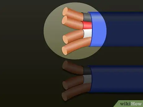
Step 5. Attach the 3-wire cable from the first switch box to the light box
Leave 20, 3 - 25.4 cm of wire in each box before cutting wires to make it easier to connect and connect to switches and lights.
A 3-wire cable has an "extra" wire when compared to a 2-wire cable, and it's almost always a red wire. This third wire is indispensable for the installation of a 3-way switch
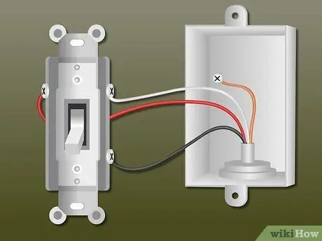
Step 6. Attach the 3-wire cable from the second switch box to the light box
Leave 20, 3 - 25.4 cm in each box before cutting the wires to make it easier to connect and connect to the lights.
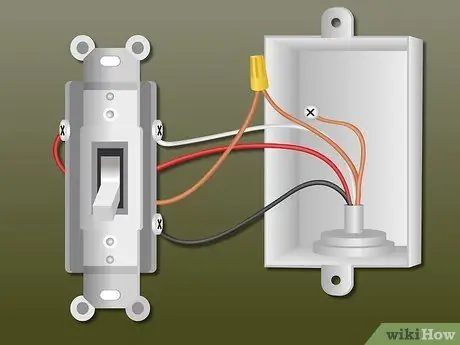
Step 7. Connect the ground wire
Provide a green wire or shorter bare wire (20.5 cm) to the group of wires connected by this wirenut to allow connection to the green ground terminal screw on each device in the box (switch, socket, lamp, etc.) - one wire for each ground terminal screw. If the switch or junction box is metal, it must also be “properly grounded” with a green ground screw or a workable ground clamp. This must be done on every box the cable enters and on any device that provides a termination point for ground.
- It is highly recommended that you complete these ground connections first, and then fold them carefully into the inside of the box - so that they don't get in the way - and leave only a bit of the ground end exposed to make connection to the device easier.
- No ground connection is made to the plastic, fiber, or other non-conductive box.
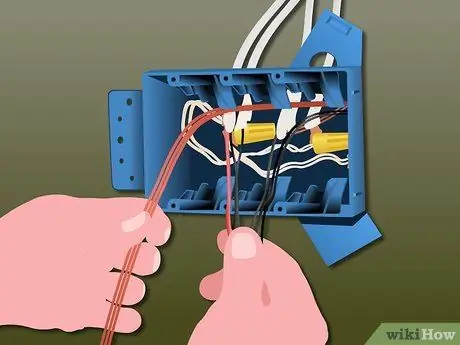
Step 8. Connect the feed wires in the first switch box
First, connect all the ground wires as described previously. The 2-wire feed wire from the mains goes to the bottom of the switch box and the hot wire (black) connects to the common or shunt terminal on the 3-way switch. There is only one such terminal on a 3-way switch, and it can usually be recognized as having a terminal screw of a different color (usually much darker) than the other two terminal screws (excluding the green ground screw).
Connect the white (neutral) wire on the 3-wire wire directly to the white (neutral) wire on the 2-wire 'feed' wire with a wirenut (not a single white wire connection to this switch)
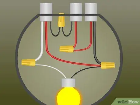
Step 9. Connect the 3-wire cable on the first switch box
The 3-wire cable enters through the top of the first switch box. Connect the red wire to one of the two unused terminal screws (shown in the figure above, located at the top left and right of both 3-way switches). It doesn't matter which terminal screw is connected to this cable.
Connect the black wire to the unused terminal screw that remains on the switch
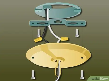
Step 10. Connect the wires to the light box
Again, connect all ground wires as described previously, if not already done. In the light box, there will be two 3-wire wires. One 3-wire wire comes from the first switch box, and the white wire acts as neutral. The other 3-wire cable comes from the second switch box, and will be the “switch leg”. Mark both ends of this wire by wrapping it with black tape to let people working on this circuit later on that this wire is no longer neutral. This is a new electrical code requirement, but is common practice whenever a white or gray wire becomes or can become electrified.
- Connect the two red wires together with a wirenut.
- Connect the black wire from the first 3-way switch and the white wire from the "switch foot" wire coming from the second 3-way switch (which is wrapped in black tape) together with a wirenut.
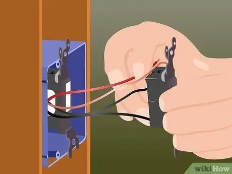
Step 11. Connect the 3 wire cable inside the second switch box to the switch
Connect all ground wires as described previously, if not already done. Connect the black wire to the shunt or screw terminal with the switch (again, the common screw terminal is a screw of a different color than the rest of the switch).
- Connect the red wire to one of the two unused terminal screws (it doesn't matter which one).
- Connect the “switch foot” (white wire with black tape) to the unused terminal screw that remains on the switch.
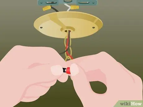
Step 12. Connect to the lamp
The light box should only have one black wire, one white wire, and one ground wire to the power source to the lamp.
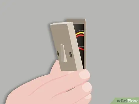
Step 13. Finish
Check the tightness of all wirenuts, and make sure there are no exposed neutral wires and hot conductors. Fold all wires carefully into the box, and fix all the devices and the light box with screws. Install the plate and cover. Restart the power source and test.
Part 2 of 3: Installation Instructions in Austria
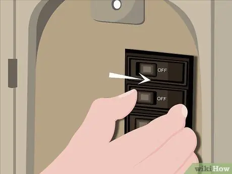
Step 1. Turn off the power source
Make sure there is no electricity in the circuit.
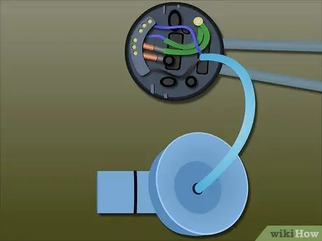
Step 2. Connect the circuit wires to the lamp
The Earth (green) and Neutral (black) circuit wires are connected to the green and blue light wires, respectively.
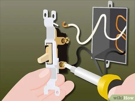
Step 3. Connect the live circuit wire (red) to the common ONE terminal switch (middle)
Connect the transfer wire (white) to Terminal 1. Connect the second transfer wire (white or red) to Terminal 2.
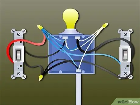
Step 4. On the switch, connect the two transfer wires (terminal 1 and terminal 2 on switch 2 respectively) and the common terminal to the red wire
This is then connected to the lamp.
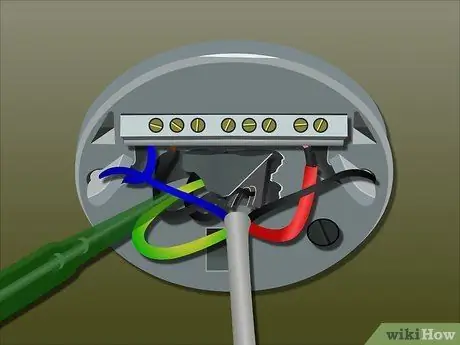
Step 5. On the lamp holder, connect the transfer cable 1 on switch 1 to the transfer cable 1 on switch 2
Then connect the transfer cable 2 on switch 1 to the transfer cable 2 on switch 2.
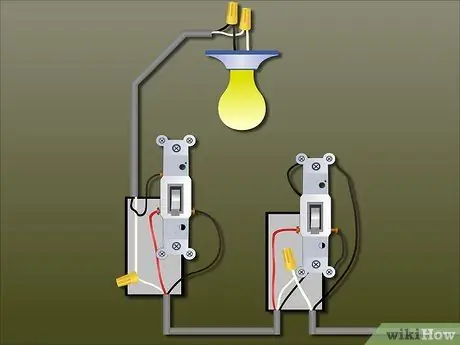
Step 6. Connect the red wire on switch 2 (connected to the terminal with switch 2) to the active terminal on the lamp holder (red or brown)
Part 3 of 3: Understanding Common Cable Types
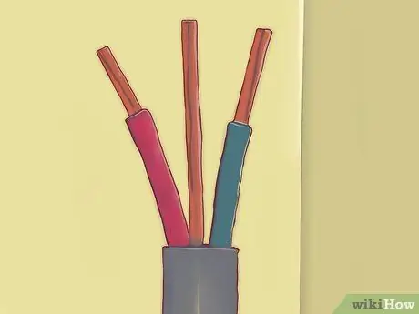
Step 1. Understand non-metallic wires
NM (also known as “Romex) and UF (“underground bait”) cables both have a plastic jacket that wraps around 2 (or more) wires - including one white wire and one black wire - and one bare wire.
- NM is used for indoors and UF is used for outdoors, in the sun, or buried in the ground.
- NM cable is easier to use than other cable types, requires no special equipment or preparation, and is less expensive. Therefore, these cables are widely used.
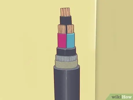
Step 2. Understand the types of armor cables, including BX, MC, and AC
Different types of armor cables are very similar to each other with only slight differences. These cables consist of a metal jacket formed by a helically bonded, interlocking layer of steel or aluminum that covers two (or more) wires - including one white wire, one black wire, and often one green wire. Armor cables that do not have a green wire use an outer metal jacket as a ground conductor.
No type of armor cable can be installed outdoors or underground
Step 3. Know the limitations of each type of cable
There are unique precautions and instructions for each cable type, and specific connectors for armor cables. For example, don't use Romex connectors on armor cables, even though many connectors look similar.
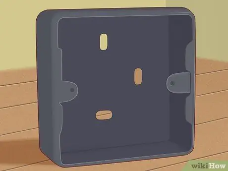
Step 4. If the power source is from an armored wire that doesn't have a full size ground wire (#12 or #14), use a metal grid to extend the ground from the armor layer to the box and to the circuit ground wire
Do this by inserting a special green hex head grounding screw into the pre-installed hole in the metal case, or using a special green ground clamp.
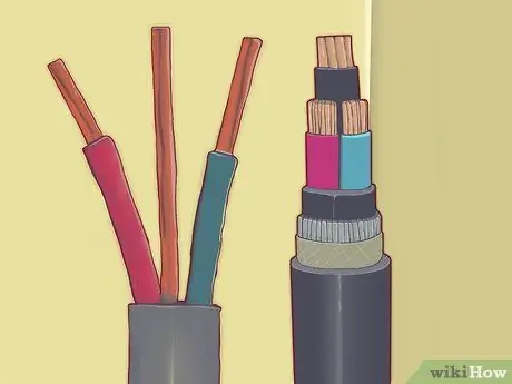
Step 5. Learn the cable naming rules
All cables have a "trade name" which is basically derived from the number of non-ground conductor wires and the type of construction. For example, a “Romex twelve (12/2)” cable has two #12 conductors, plus one full-size #12 ground wire. The “BX fourteen three (14/3)” cable has three #14 conductor wires, plus one full size #14 ground wire.
Tips
- Never install cable sizes on circuits protected by breakers or fuses that have a capacity greater than the cable you are using: sizes 6 - 50 A, sizes 8 - 40A, sizes 10 - 30A, sizes 12 - 20A, sizes 14 - 15A. Do not connect smaller wires to the electrical panel, unless they are converting ends for a doorbell or similar circuit.
- Detect and treat problems with switches differently depending on the relative placement of the switches and the power source.
- One wire per terminal. Do not connect more than one wire under the screw terminals. In addition, the wire should loop around the screw clockwise. Only wrap solid wire around the terminal screws. Fiber wire will require fork terminals or rings to be attached (crewed or soldered) to the wire and terminal screws to be tightened on the fork terminals or rings.
- The “black wire holder” option available on some switches and sockets makes it easier for people to insert bare wire into the holes for connection without needing to unscrew. Over time, these pressure connections decrease and eventually fail, so the use of screw terminals is preferred.
- It is not necessary to use branching of the #12 wire from an existing #14 wire circuit. A size 12 wire is required by the code for sockets and other appliances (dishwashers, refrigerators, etc.) in kitchens and dining areas that require 20A service (some bathrooms use #12 wire to support hairdryers, etc., but this is not required).
- Use a copper #14 (size 14) Romex cable which is smaller, easier to use, and less expensive if the circuit is protected by a 15 amp fuse or circuit breaker. Very few three-way circuits transfer load on a 20 amp circuit.
- When renovating a home, always check the fuses or circuit breakers where new lights or sockets are installed.
-
The 120V / 15A circuit is built to support up to 1440 watts of continuous load (heat, lights, etc.), so you'll need enough lights to get through the maximum 15A/ #14 circuit. In comparison, the 120V/20A circuit is built to support up to 1920 watts of continuous load (heat, lights, etc.). If a larger load is to be connected, also larger wires and circuit breakers or fuses must be installed.
The circuit's maximum load - in this case watts - is specified as Volts X Amps X.80, where volts and amps are specified and.80 is required by the code to reduce the circuit's capacity to 80% of the maximum. It can be said that the maximum amperage of a 15 amp circuit is 12 amps using a similar formula: Circuit Breaker/Fuse X.80 = maximum amp load. Same is the case with a 20 amp circuit: 20 X.80 = 16 amps
Warning
- Remember to turn off the power source before you start doing electrical work.
- Check the electrical grid installation regulations in your area, as the electrical grid system in your area may use a different color combination.
- Never mix wire sizes and materials (copper and aluminum).


